
?» The stepper motor driver Creative Works of Tom McGuire
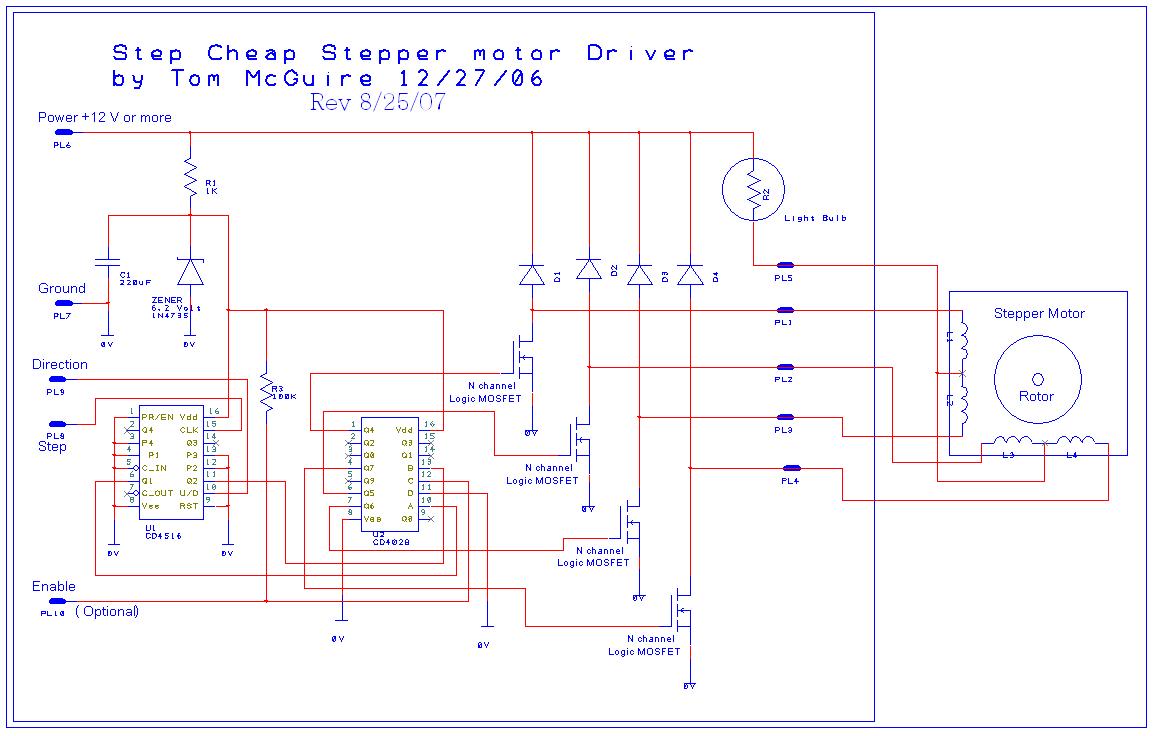
This circuit is suitable for driving 5 or 6 wire unipolar stepper motors, which are commonly used in various applications requiring precise control of position and speed. The design accommodates a voltage supply range from 9V to 24V, offering flexibility for different motor specifications.
The breadboard layout allows for easy prototyping and testing, while the option for a PCB layout caters to users looking for a more robust and permanent solution. For applications requiring multiple motors, such as in CNC machines or 3D printers, three identical circuits can be implemented to control the X, Y, and Z axes, ensuring synchronized movement.
In terms of motor performance, the example calculation provided demonstrates how to determine the appropriate wattage for the motor based on its voltage rating and resistance. This is crucial for selecting the correct load for the circuit. By using a bulb rated at approximately 6 watts, the circuit can simulate the motor load, allowing for effective testing and adjustment before connecting the actual motor. The recommendation to use a 24V power supply ensures that the motor operates efficiently, leveraging the full potential of its design.
Overall, this circuit design is practical for hobbyists and professionals alike, offering versatility in motor control applications while facilitating straightforward assembly and testing.This is designed to work with a varity of stepper motors, 5 or 6 wire unipolar types. Its also made to operate from about 9 volts to up to about 24 volts. Below is a bread board layout of the circuit but I can offer a PC board layout for those of you who want something a little more professional. You will need 3 of these for the X, Y, and Z motors . Onenice thing about this circuit is if you have a motor that is rated for 12 volts and has a resistance of 24 ohms then calculate the wattage of the motor like so: 12 * ( 12/24 ) = 6 Watts. Then put something close to a 6 watt bulb in the socket. Then use a 24 volt ( 12 * 2 ) power supply to run the circuit. It`s an easy way to get a more or less optimum preformance out of the motor. 🔗 External reference
Related Circuits
The circuit depicted will automatically switch ON and OFF at night and morning, respectively. In this circuit, R1 can be adjusted to change the sensitivity. The operation of the circuit is straightforward. The Light Dependent Resistor (LDR) exhibits very...
The LED circuit below is an example of using 25 white LEDs in series connected to the 120VAC line. It can be modified for more or less LEDs by adjusting the resistor value. The exact resistance will depend on...
The LT1206 is designed to drive multiple video cables, featuring a bandwidth of 60 MHz, an output current capability of 250 mA, and low output impedance. The LT1206 operational amplifier is optimized for video signal applications, making it an excellent...
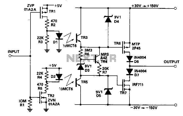
This circuit accepts a signal from a 5-V CMOS logic circuit and produces a high voltage of the same polarity. The high-voltage supply can be adjusted between ±30 V and ±150 V without requiring any changes to the circuit...

The circuit is ideal for high-frequency line driving systems that necessitate a wide power bandwidth at elevated output current levels. The integrated circuit used is HA2530. The bandwidth of the circuit is constrained solely by the single pole response...

The circuit comprises a trigger circuit, an alarm control circuit, and a reset circuit for the alarm. The trigger circuit includes mercury switches (S1), a resistor, transistors (V1), and a relay (K1). The alarm control circuit is made up...