
two-speed motor contactor control circuit two speeds in the same direction
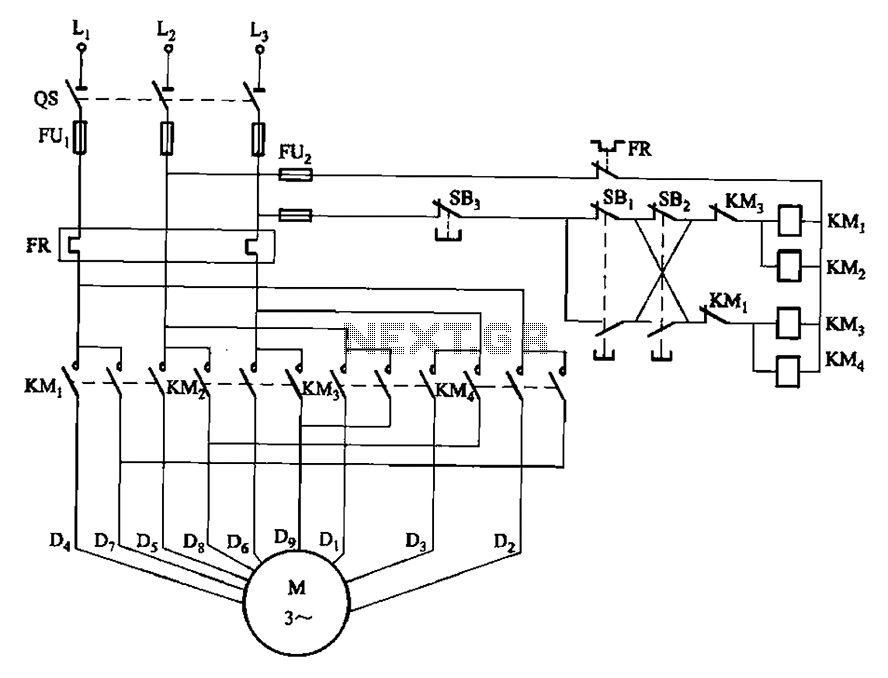
The circuit design incorporates two operational buttons, SBi and SBz, that control the speed of a motor or similar device. SBi is designated for the first speed setting, while SBz is utilized for the second speed setting. Both buttons are configured to allow the device to operate at two distinct speeds in the same directional flow, enhancing versatility in applications that require varying operational speeds.
In typical implementations, SBi and SBz may be connected to a motor driver circuit that interprets the button presses and adjusts the power supplied to the motor accordingly. The circuit could utilize a microcontroller or a dedicated speed controller IC to manage the input from the buttons and modulate the output to the motor.
The first speed setting, activated by SBi, may provide a lower voltage or PWM (Pulse Width Modulation) signal to the motor, resulting in a slower rotational speed. In contrast, the second speed setting, controlled by SBz, could increase the voltage or modify the PWM duty cycle, allowing for a higher speed operation.
Additionally, protective components such as diodes may be included to prevent back EMF generated by the motor from damaging the circuit. Capacitors may also be employed to filter noise and stabilize the voltage supply, ensuring smooth operation at both speed settings.
This circuit design is applicable in various scenarios, including robotics, conveyor systems, and other automated machinery where speed control is essential for performance optimization. Circuit shown in Figure 3-112. Figure, SBi as the first speed operation button, SBz is run by the second speed class. Two speeds in the same direction.
Related Circuits
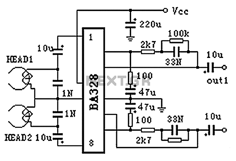
The BA328 is a dual preamplifier circuit designed with minimal external components, facilitating straightforward installation within a single 8-pin DIP package. The circuit features a wide operating voltage range, low noise levels, and high open-loop gain, ensuring good balance...
The circuit designed for distortion measurements eliminates the fundamental frequency of 1 kHz, enabling the assessment of the residual harmonic levels. Initially, a true RMS meter is employed to measure the 1-kHz input level (E^) by positioning the switch...
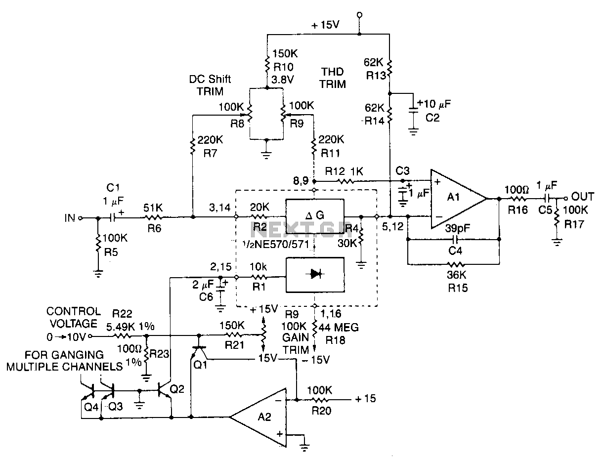
This typical circuit utilizes an external operational amplifier for improved performance, along with an exponential converter to achieve a control characteristic of -6 dB per volt. Trim networks are incorporated to eliminate distortion and offset, as well as to...
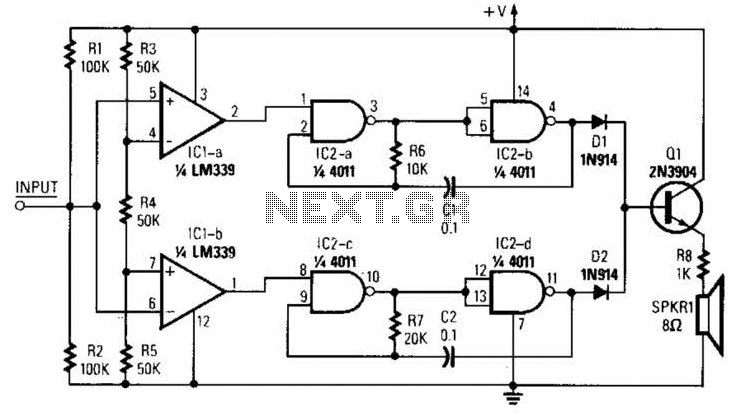
This circuit was developed in response to requests from website visitors for a timer that can emit a beep after intervals of one, two, three minutes, and so forth, for jogging purposes. As depicted in the circuit diagram, SW1...

This 555 timer circuit temperature monitoring system project can monitor temperature at up to four points. The system allows for the selection of whether the alarm should be triggered when the temperature increases or decreases, depending on the resistance...
A capacitance meter is an essential instrument for electronics hobbyists and professional electronic technicians. A capacitance meter is a specialized device used to measure the capacitance of capacitors in electronic circuits. It is a valuable tool for diagnosing and troubleshooting...