
oscillator VCO sawtooth and duty cycle
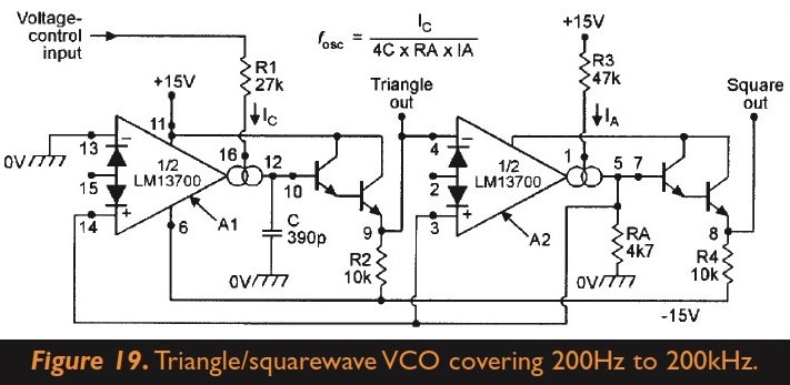
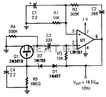
The circuit in question utilizes an oscillator to produce square and triangle waveforms. The base design typically incorporates components such as operational amplifiers or integrated circuit timers, which generate these waveforms through their inherent characteristics. To enhance functionality, the addition of diodes and a potentiometer can be considered.
Incorporating diodes into the circuit can facilitate waveform shaping. For instance, by placing diodes in specific configurations, it is possible to create a ramp or sawtooth waveform from the triangle wave output. This is achieved by controlling the charging and discharging paths of the waveform, allowing for adjustments in slope and amplitude.
The introduction of a potentiometer can serve multiple purposes. It can be integrated into the feedback loop of the oscillator to adjust the duty cycle of the square wave output. By varying the resistance of the potentiometer, the ratio of the high and low states of the square wave can be modified, thus achieving the desired duty cycle.
To implement these modifications, the following steps can be taken:
1. Identify the output stage of the oscillator where the square and triangle waves are generated.
2. Connect the potentiometer in such a way that it influences the feedback or timing components of the oscillator, allowing for duty cycle adjustments.
3. Integrate the diodes in a manner that alters the triangle wave output to create the desired ramp or sawtooth effect, ensuring that the diodes are oriented correctly to allow current flow in the intended direction.
It is essential to consider the specifications of the components used, including the maximum voltage and current ratings of the diodes and the resistance range of the potentiometer, to ensure compatibility with the existing circuit. Additionally, simulations or prototyping may be beneficial to verify the effectiveness of these modifications before final implementation.The circuit generates square and triangle wave. I wonder if I can add a couple of diodes and a potentiometer to be able to skew between triangle-ramp/saw and change the duty cycle of the square wave Is it that simple 🔗 External reference
Related Circuits
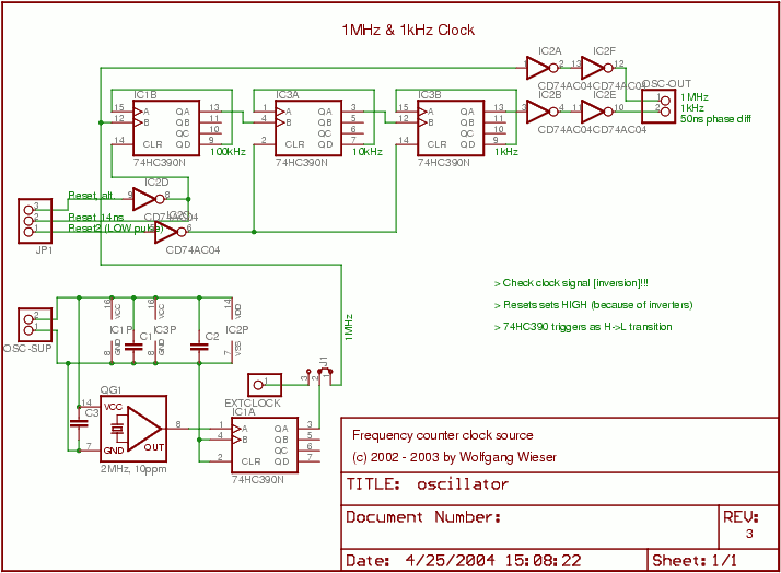
The oscillator generates a 1 MHz and a 1 kHz clock signal. The 1 MHz clock serves as the primary clock for the microcontroller and provides a time base for millisecond measurements. A 2 MHz signal is divided by...

A CD4017 is configured as a senary counter, with an input clock frequency of 300 Hz. Diodes VD1 to VD9 and resistors R1 to R3 form three three-input OR gates, which can each receive two 50 Hz three-phase wave...
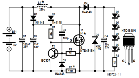
Before getting started, an acknowledgment is due. The circuit presented here employs an innovative method of controlling a flyback converter using the voltage developed across a current-sensing resistor. This approach was published by Andrew Armstrong in the July 1992...
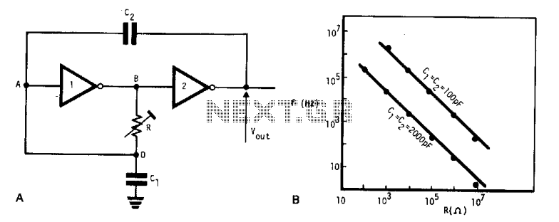
This simple, low-cost oscillator is constructed using two CMOS buffer inverters, two capacitors, and a variable resistor. The circuit operates with voltage levels ranging from 4 V to 18 V. When C1 equals C2, the frequency of oscillation is...
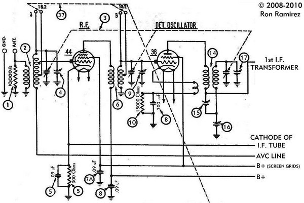
The initial step involves taking notes to indicate which wire connects to each terminal on the 36 tube socket. Remove all wires connected to the 36 tube socket. Next, drill out the rivets that secure the five-pin 36 tube...
This Wien-bridge sine-wave oscillator utilizes a 2N3819 as an amplitude stabilizer. The 2N3819 functions as a variable-resistance element within the Wien bridge. The Wien-bridge oscillator is a type of electronic oscillator that generates sine waves. It employs a bridge circuit...