
1-20 minutes a timing circuit

The described system employs a multi-gear stick control mechanism that allows for the selection of various operational states. The primary component, an integrated circuit (IC), serves as a self-excited multivibrator, which is critical for generating oscillations necessary for timing and control functions. This IC is capable of producing binary pulses, which are essential for managing the operation of the system across a specified range of liter measurements.
The operational states are determined by the configuration of switch S2. In state "1," the frequency division ratio is set to 21_8192, which provides a specific timing mechanism allowing for precise control over the system's operation. This configuration enables the system to execute timing functions that can be cut to intervals of 1.2 for every twenty clock cycles, facilitating a high degree of accuracy in time management.
When switch S2 is adjusted to state "3," the frequency division ratio alters to 81920. This change significantly impacts the timing capabilities of the system, allowing for extended operational periods ranging from 100 minutes to 20 hours. Such flexibility is crucial for applications requiring varying durations of operation, making the system versatile for different tasks.
The overall design of the circuit integrates these features to ensure reliable performance and adaptability. The self-excited multivibrator plays a vital role in maintaining the oscillation necessary for the timing functions, while the multi-gear stick provides user-friendly control over the operational states. This combination results in a robust electronic schematic capable of meeting diverse timing requirements in various applications.10 minutes to 2 hours: 100 lines bell - 20 Ogawa, when selected by the multi-gear stick lemma Ge S2 41f system. IC} is self-excited multivibrator. 1C, the evolution liter dC device. IC 3 to 14 liters of binary pulses f Pi device. When turned} rxsi called, 1iI RYl Chih-what is it s station, will be called " the beginning. If S2 is set r" 1 "state archives, the frequency division ratio of 21_8192, then given time to cut bone I.2 twenty clock .S2 dry "3" file, the frequency division ratio is 81920. In this case the timing when asked to 100 minutes - 20 hours.
Related Circuits
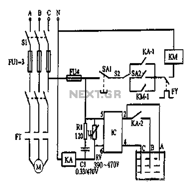
An automatic water tank system is illustrated in the circuit diagram. The circuit employs a PSSR AC solid-state relay, which is a new type of solid-state relay designed for AC applications. Unlike traditional solid-state relays (SSR), this PSSR not...
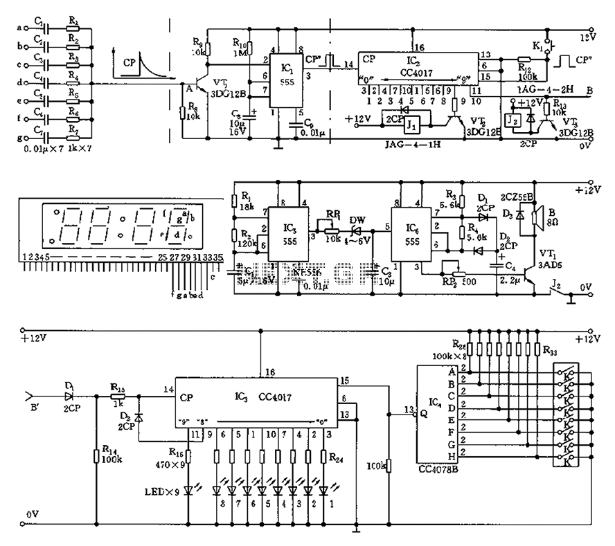
This circuit is primarily designed as a timely reminder system for monitoring individuals on duty who may fall asleep. It features a detection circuit that processes minute signals. As the LED digital electronic timing clock displays the minute, the...
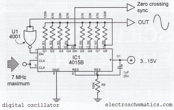
The digital sine wave generator (oscillator) circuit requires only a few components to produce signals with high amplitude constants and a wide range of variable frequencies. This circuit generates a sine wave signal, and by altering the values of...
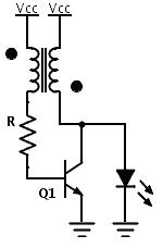
Previously, a boost circuit was tested that enables the powering of a 3 V LED using a discharged battery (approximately 1 V or lower). This circuit consists of a single transistor, one resistor, and a small transformer with a...
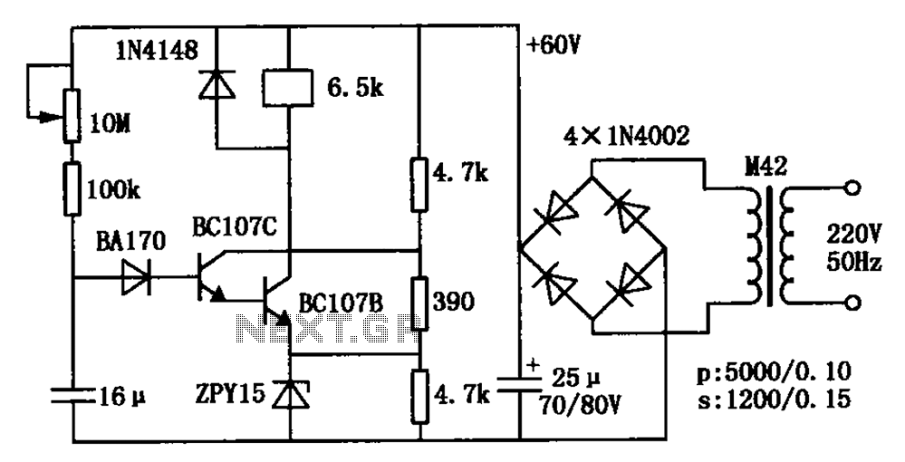
The circuit is a relay delay pull transistor configuration. Initially, when powered, the 16 µF capacitor has a voltage of zero, resulting in both transistors being off, and the relay remains inactive. As the 16 µF capacitor charges over...
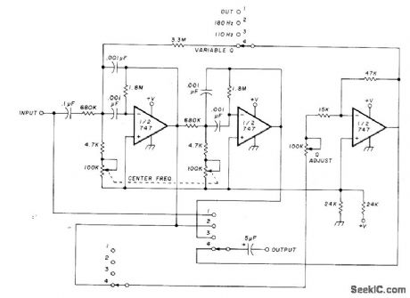
The circuit utilizing Optical Electronics 9803 operational amplifiers separates an audio frequency (AF) input signal into two outputs. The low-pass output allows frequencies from DC up to 10 Hz, while the high-pass output encompasses frequency content above 10 Hz,...