
Multimeter AC voltage measuring circuit
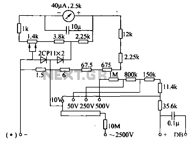
The voltage converter circuit is designed to facilitate accurate voltage measurements across different ranges, particularly for both AC and DC voltages. The use of a selector switch allows users to easily switch between voltage ranges, accommodating various measurement requirements. The inclusion of shunt and series resistors plays a crucial role in adjusting the sensitivity of the measuring device to ensure precise readings. The shunt resistor, positioned in parallel, maintains the integrity of the DC voltage profile while the series resistor modifies the overall resistance in the circuit, affecting the sensitivity.
The half-wave rectifier circuit is a fundamental aspect of this design, although it is acknowledged that its efficiency may be lower compared to other rectification methods. The additional resistance introduced not only impacts the voltage profile but also serves to distribute the voltage more evenly across the circuit components. This design consideration is essential for achieving accurate measurements, particularly when dealing with high voltages.
For high voltage applications, the circuit is equipped to handle up to 2500 V, which necessitates the use of a high-value resistor (10 MΩ) to prevent excessive current flow that could damage the measuring equipment. The adjustable drive switch enhances the versatility of the circuit, allowing for a range of voltage settings from 10 V to 500 V, suitable for various testing scenarios.
The integration of a smoothing capacitor (10 µF) is a critical enhancement for the circuit, as it mitigates fluctuations in the rectified voltage. This is particularly beneficial when measuring low-frequency signals, as it helps to stabilize the readings and prevent erratic behavior of the measuring device, thereby improving the reliability of the measurements taken. Overall, this voltage converter circuit is a well-thought-out design that balances efficiency, accuracy, and versatility in voltage measurement applications.Measuring the voltage converter can be set to switch to the right, left AC voltage range selector switch to any one file, then the measurement circuit , as shown in FIG. In this case the shunt resistor in parallel with the header, and the DC voltage profile is still the same, just another of a series resistor 2. 25kfl. Then 3. 8kn shunt resistor, so the meter when measuring DC voltage sensitivity than decrease. The table half-wave rectifier circuit, low rectification efficiency. However, because of the additional resistance and additional resistance DC voltage share, such as the exchange of additional resistance 250V profile just as an additional electrical DC voltage 50v profile resistance, a difference of up to 5 times.
Visible voltage sensitive AC voltage profile of one-fifth of the DC voltage. 2000fl / V 5 = 4000 / V This was the way to reduce the resistance of the additional compensation due rectifying current inefficiencies leaving meter drop. AC and DC voltage to achieve consistent pressure scale. AC high voltage test 2500V, lOMfl additional resistor with specially equipped. Connected to the high voltage or "2500V and" * "between the two jacks, the amount of drive switch 10 ~ 500V can be placed in any one file.
In addition header in parallel with a lOfF electrolytic capacitor for smoothing the rectified pulsating voltage, the multimeter when measuring low frequency lower than 10Hz, the pointer is not to shake.
Related Circuits
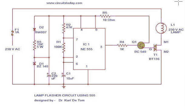
This circuit diagram represents a lamp flasher powered by mains electricity. It is capable of flashing lamps with a maximum power of 200 Watts at user-defined rates. The NE555 integrated circuit is configured as an astable multivibrator, generating the...
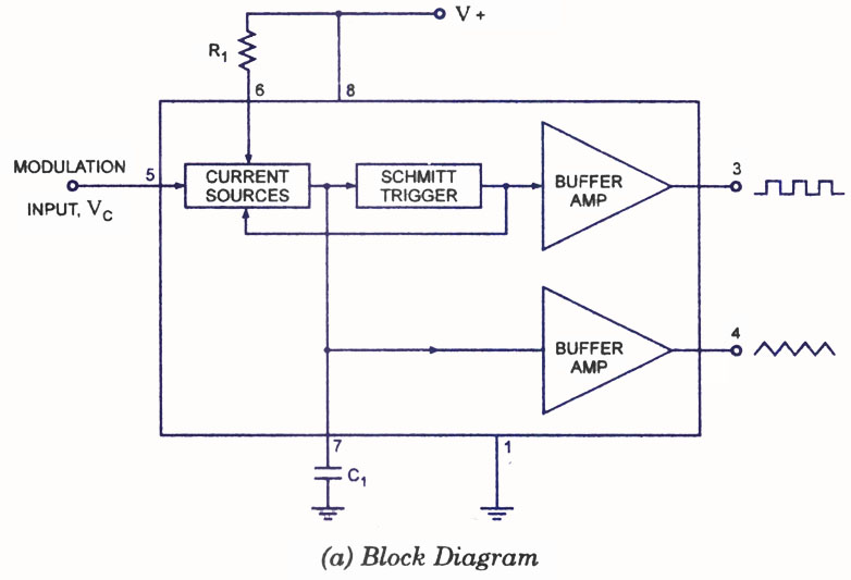
A voltage-controlled oscillator (VCO) is a type of oscillator in which the frequency of output oscillations can be adjusted by varying the amplitude of an input voltage signal. VCOs are commonly utilized in frequency modulation (FM), pulse modulation (PM),...
The soil moisture meter circuit is useful for monitoring the moisture levels in plants. It is a simple and effective circuit. The soil moisture meter circuit is designed to measure the volumetric water content in soil, providing valuable data for...
The principle utilized in this electronic head or tail circuit is straightforward: a multivibrator controls a flip-flop. The multivibrator oscillates as long as the button S1 is pressed, while the flip-flop toggles on and off at a frequency of...
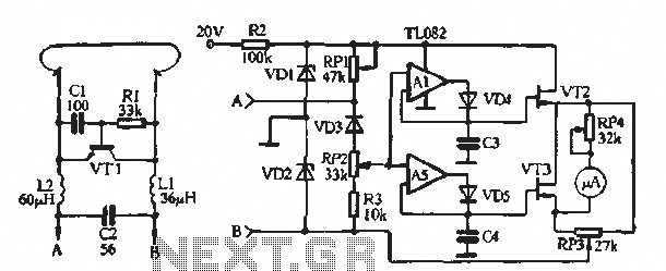
The circuit illustrated in Figure (A) consists of resistors R1 and R2 with values ranging from 15 to 18 kΩ, and capacitors C1 and C2 with capacitance values between 0.01 µF and 10 µF. Figure (B) depicts the oscillation...
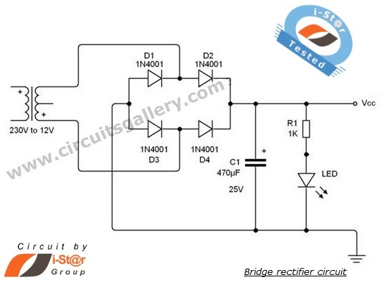
A rectifier is an electronic circuit that converts AC voltage to DC voltage. It can be implemented using a combination of capacitors and diodes. The unique property of diodes, which allows current to flow in a single direction, is...