
RF Modulator Circuit Composed of TA7673
The RF modulator circuit is designed to convert baseband video signals into radio frequency (RF) signals suitable for transmission over coaxial cables. The TA7673 integrated circuit serves as the core of the modulator, facilitating the modulation process through its internal architecture. The circuit typically includes components such as resistors, capacitors, and inductors that work together to filter and amplify the signal, ensuring high-quality output.
In operation, the modulator receives composite video input, which is then processed to create an RF output. The modulation technique employed can vary, but it often involves amplitude modulation (AM) or frequency modulation (FM) to encode the video signal onto a carrier frequency, typically within the VHF or UHF bands. The output can be connected directly to a television or other RF-compatible devices.
The design also incorporates power supply considerations, ensuring that the modulator operates efficiently and reliably. Proper grounding and shielding techniques are essential to minimize interference and maintain signal integrity. The circuit can be adapted for various applications by modifying the output frequency or adjusting component values to meet specific requirements.
Overall, the RF modulator circuit is an essential building block in modern electronic systems, enabling the seamless transmission of audio-visual content across different platforms and devices.The RF modulator is the very important component in TV, VCR, satellite receiver, format converter, home computer and game machine. This circuit is simple, stable and easy to make, it can be easily connected with a lot kinds of circuit boards.
The figure is the circuit of RF modulator, ICl is the modulator ASIC (TA7673), the 10-pin and 11-pin generate the ima.. 🔗 External reference
Related Circuits
This circuit is an automatic street light controller. The sensor used to detect changes in light is an LDR (Light Dependent Resistor). The working principle of the LDR is that when exposed to light, its resistance value decreases, while...

A simple remote control tester circuit with a diagram and schematic using the infrared sensor IC TSOP1738. An LED will blink when infrared waves fall on it, indicating the remote control is functioning. The remote control tester circuit utilizes the...
The Implantable Lamp (A3024) is a radio-controlled lamp powered by a battery. Once encapsulated in epoxy and silicone, it is waterproof and compact, allowing it to be implanted in an animal. The A3024 can theoretically be activated by any...

Men, in particular, appreciate the convenience of television remote controls, which can often lead to frustration for their female partners. Men seem to have a desire to understand what... The initial statement highlights a common dynamic in household technology usage,...

The following circuit illustrates a Repeating Interval Timer Circuit Diagram. This circuit is based on the CMOS 4060 integrated circuit (IC). Features include a 6-pin output. The Repeating Interval Timer Circuit utilizing the CMOS 4060 IC is designed to generate...
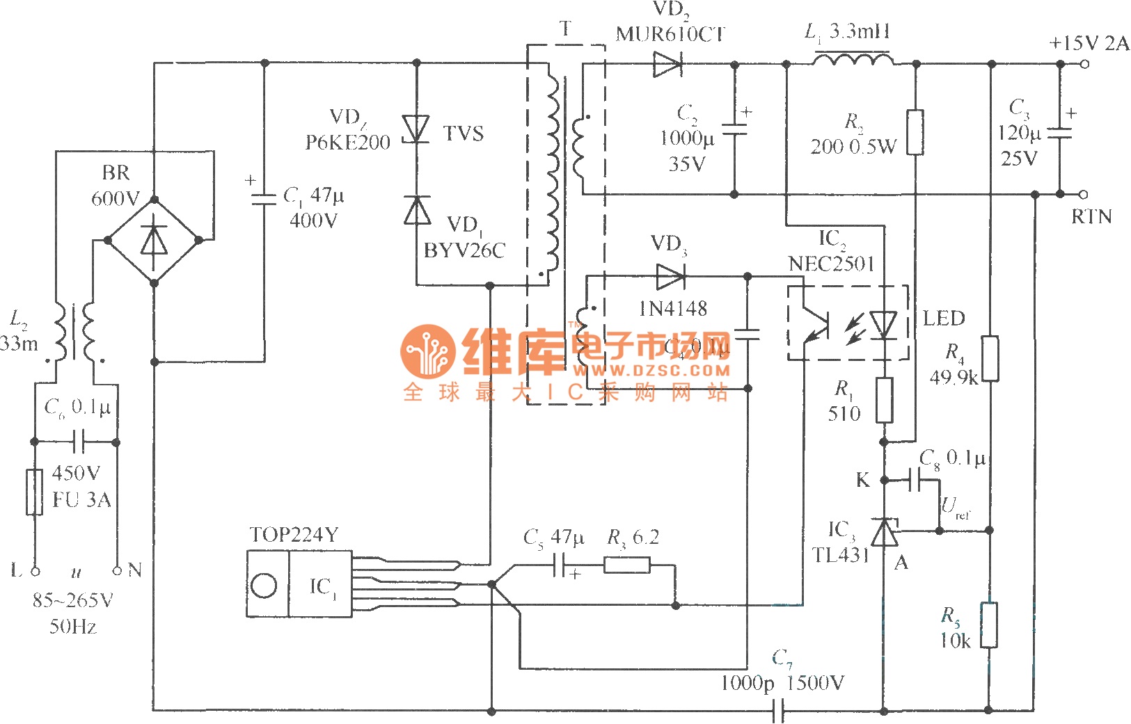
This document presents a 30W micro switch regulated power supply utilizing the TOP224Y integrated circuit. The circuit diagram illustrates its design. A notable feature of this power supply is the use of the TL431 component to replace the regulation...