
rf module based remote control

To transmit control signals, specifically Dual Tone Multi Frequency (DTMF) signals, an RF transmitter and receiver pair is required. An FM transmitter and receiver or any RF TxRx module can be utilized. In this project, an Amplitude Shift Keying (ASK) modulated RF transmitter and receiver pair is employed for signal transmission.
The integrated circuit (IC) UM91214B serves as a DTMF tone generator. This single-chip IC features an on-chip oscillator designed for a 3.58 MHz crystal and is capable of generating dialing pulses (DP) and DTMF tones. For this application, the focus is solely on DTMF signal generation. A keypad interface is necessary to produce various DTMF tones, and the UM91214B includes an integrated keypad interface. The keypad pins must be connected to the row and column pins of the UM91214B. Upon pressing a keypad button, a corresponding DTMF tone is generated at pin 7. To verify the generation of the DTMF tone, an 8-ohm speaker can be connected; pressing a button will allow the tone to be heard. It is important to note that the UM91214B is compatible with a 4x4 matrix keypad. However, the 16th button, intended for redialing, does not generate a DTMF tone and can be omitted from the column configuration for buttons labeled A, B, C, and D.
The schematic for this remote control system would include the following components: an RF transmitter and receiver module, the UM91214B IC, a 4x4 matrix keypad, and an 8-ohm speaker. The RF transmitter will be connected to the output pin of the UM91214B, allowing DTMF signals to be transmitted wirelessly. The receiver will decode the signals sent by the transmitter and control the connected devices accordingly. Power supply considerations must be made for each component, ensuring that the voltage and current ratings are adhered to. Proper layout and grounding practices should be followed to minimize noise and ensure reliable operation. Additionally, the range of the RF transmission can be optimized by selecting appropriate antennas for both the transmitter and receiver modules.Remote controls are part of an electronics device used for operating the device remotely. Remote control has continuously evolved and advanced over recent years. The technologies likebluetoothconnectivity, motion sensor enabled capabilities and voice control have been included to remote controls. Here we are going to build a remote control. This r emote control could be used for controlling robo cars, helicopters or for switching home appliances. Normal remote controls use IR transmission, butinthiscaseRF transmission is used. Transmission through RF is better than IR (infrared) because of many reasons. Firstly, signals through RF can travel through larger distances making it suitable for long range applications. Also, while IR mostly operates in line-of-sight mode, RF signals can travel even when there is an obstruction between transmitter & receiver.
Next, RF transmission is more strong and reliable than IR transmission. RFmodule: For the transmission of control signals (here DTMF signals) we need a RF transmitter and a receiver. FM transmitter and receiver pair or any kind of RF TxRx module will do. In this remote control ASK modulation based RF transmitter & receiver pair are used for transmitting signals.
Get information about ASK module : click here. . IC UM91214b( DTMF TONE GENERATOR): This is a single single chip IC with an on-chip oscillator for a 3. 58Mhz crystal. This is capable of generating Dialing Pulse(DP) and Dual Tone Multi Frequency(DTMF). But we don`t need to be bothered about DP generation. All you need is just to generate DTMF signals. A keypad interface is necessary to generate different DTMF signals. The advantage of using UM91214b is its inbuilt keypad interface facility. You just have to connect the keypad pins to UM91214`s Row & Column pins. Download UM91214 datasheet from here. Whenever a keypad button is pressed, a DTMF tone is generated on pin7 accordingly. To check whether DTMF tone is being generated or not, simply just connect a 8ohm speaker, press a button and hear the tone.
N. B. : UM91214 is compatible for 4x4 matrixkeypad. But pressing 16th button won`t generate any DTMF tone, it is for redialing, we don`t need this function, we can omit the column for ABCD. 🔗 External reference
Related Circuits
This document outlines modifications made to the RIG RX-2 receiver, enabling remote control via a computer using an RS-232 serial interface. The modifications consist of two components: additional hardware and a new firmware program for the PIC16C84 microcontroller. In...

Personal safes are innovative locking storage solutions that open with a simple touch of a finger. These devices are designed as secure storage options for medications, jewelry, firearms, documents, and other valuable or potentially hazardous items. They employ fingerprint...
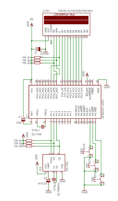
The HC-06 module is a slave mode serial Bluetooth data link manufactured by CSR. In this project, a mobile phone communicates with the AT89C2051 microcontroller via the HC-06 module. The complexity of the communication has been encapsulated within a...
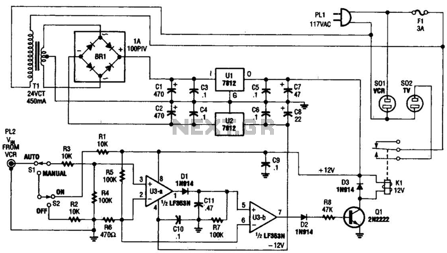
This circuit detects the video signal from the VCR. When the VCR is powered on, the video signal is amplified by U3A to drive Q1, which activates K1. This setup eliminates the need to manually turn on and off...
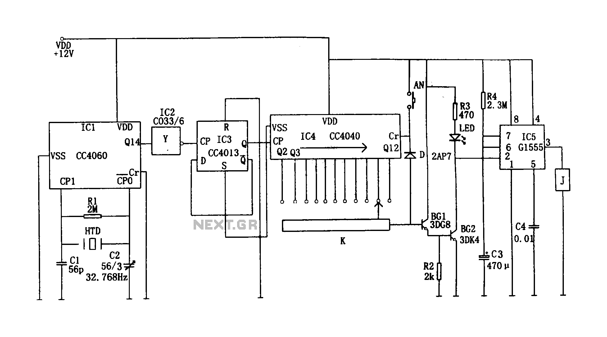
This circuit illustrates a precision digital timing control system. The controller includes a crystal oscillator circuit, a divider, a counting circuit, and monostable flip-flops. The crystal oscillator circuit features a series of 14 binary counters/dividers, a watch crystal operating...
The shaft can be positioned at specific angular positions by sending a coded signal to the servo. As long as the coded signal is present on the input line, the servo will maintain the angular position of the shaft....