
Serial Remote Control for the RIG RX-2 Receiver

The modifications to the RIG RX-2 receiver introduce a robust control mechanism that significantly enhances its functionality. The integration of an RS-232 serial interface allows for seamless communication between the receiver and a computer, facilitating remote operation. The design emphasizes simplicity, ensuring that the hardware modifications do not complicate the existing circuitry. The firmware programmed into the PIC16C84 microcontroller is essential for interpreting commands and managing the receiver's operations.
In terms of hardware, the use of an opto-coupler ensures electrical isolation between the receiver and the computer, protecting both devices from potential damage due to voltage differences. The shared pin for both the push-button and serial input is an efficient use of resources, minimizing the number of required connections while maintaining functionality. The decision to operate at a fixed baud rate of 1200 without flow control simplifies the communication protocol, making it accessible for users with varying levels of technical expertise.
The firmware's command structure is designed to be intuitive, allowing users to quickly navigate through channels and control scanning operations. The ability to expand the number of channels available through the 'F' command adds flexibility to the receiver's operation, accommodating various user needs. The implementation of a simple button press mechanism for channel advancement and scanning control enhances user experience, making it straightforward to operate.
Overall, the modifications to the RIG RX-2 receiver not only preserve its original capabilities but also significantly extend its functionality, making it a versatile tool for users requiring remote control and monitoring capabilities in their applications.This page describes my modifications to the RIG RX-2 receiver which enable it to be controlled remotely from a computer, using an RS-232 serial interface. The modifications are in two parts: some simple additional hardware, and a new firmware program for the PIC16C84 microcontroller.
In manual control mode, the modified receiver operates very much as the original. When the RX-2 is switched on, it will emit a 1 second beep, during which all the display segments are turned (`lamp test`). This allows time for the signal detector circuit to settle. After the settling period, it will start scanning from channel 1, stopping only when it finds a signal.
When a signal is found, the RX-2 emits a longer beep and stops scanning, until 15 seconds after the signal is lost. It then emits a short beep and re-starts scanning. A short button press at any time will jump to the next channel and stop scanning, accompanied by a very short beep.
A longer press will re-start scanning, with a longer beep. At the same time, any characters which arrive at the serial port are checked for valid commands. There are two valid commands: `s` (or `S` - case is not important) and `F`. The `F` command, followed immediately by a channel number 0 to 9, will change to that channel, and stop scanning, if a scan was in progress. `S` will re-start scanning. No carriage return or line feed is required after the command. Any incomprehensible or extra characters are quietly ignored. In manual operation, the modified RX-2 uses the same 5 channels as the original. However, there are 5 additional channels available to the `F` command. The frequencies as supplied are shown below, but are very easily changed. The serial interface is designed to make the minimum demands on the computer driving it. It does not use any flow control: it operates at a fixed 1200 baud, and can handle continuous characters at this speed.
There are no `handshaking` signals. It cannot even send any data to the computer! The source code for the modified PIC program is available here. This requires Microchip MPLAB/MPASM to assemble, and a suitable device programmer for the PIC16C84. I am currently trying to arrange for a supply of ready programmed devices, via RIG. Until then you will need to program your own. For convenience, here is the Intel HEX format ready for the programmer. The software operation is based on the idea that when a person presses the button, it stays `down` for a long time - at least a long time compared to the duration of a serial character. The serial input and push button use the same pin. The program waits for a `low` logic level on this pin. This could either be the start of a serial character or the start of a button push. The software first attempts to decode the signal as a character. If the input is still low at the end of the character period, when it ought to be high, the software decides that it has a button push.
Two separate tasks handle the button pushes and decode the received characters. For those who are interested, there is a more detailed explanation available. The hardware modifications have been kept as simple as possible. The serial interface uses the same PIC input pin currently used by the push-button, and can be operated in conjunction with the button. It requires no extra power supply, drawing what power it needs from the PC and through the pull-up resistor on the push-button input.
In the RS-232 `idle` state, DB-9 pin 2 will sit at a voltage of -5V to -12V. The opto-coupler LED will be off, and so will be the transistor. Pin 4 will be pulled up to +5V by the push-button pull-up resistor on the RX-2 circuit board. A button push will take this point low to GND, unaffected by the presence of the serial interface. When an RS-232 character comes along, the start bit will take DB-9 pin 2 to between +5V and +12V, turning on the opto-coupler LED and transistor. The push-button input will go low, to 🔗 External reference
Related Circuits

This circuit utilizes an MC3392 low-side protected switch along with an MC1455 timing circuit to create a dimmer control for automotive instrumentation panel lamps. The brightness of incandescent lamps can be adjusted by applying Pulse Width Modulation (PWM) to...

A partial solution to reducing noise from PCs can be achieved by lowering the speed of internal cooling fans. Low-cost fan speed controllers are available, but they often utilize inefficient, heat-generating linear regulators and lack a temperature feedback mechanism....

The switching circuit consists of a buck rectifier circuit, a bistable trigger circuit, and a thyristor control circuit, enabling remote control for electrical equipment to be turned on or off. The buck rectifier circuit supplies the controller with a...

During nighttime, when no light falls on LDR1, it offers a high resistance at the base junction of transistor T1. Consequently, the bias is significantly reduced, and T1 does not conduct. This effectively removes the common terminal of IC1...
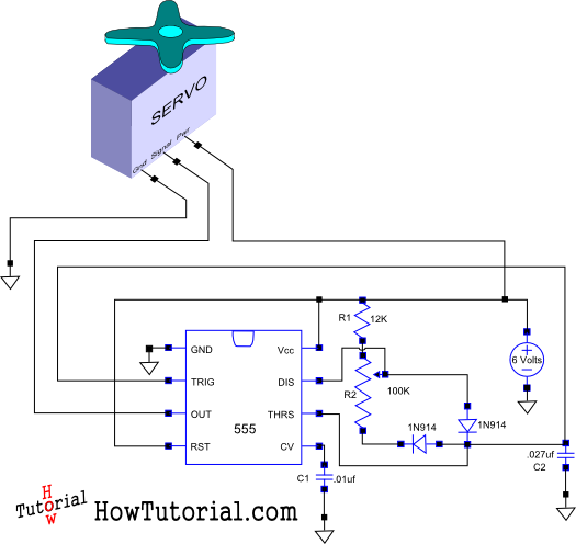
This document outlines the design of a simple circuit that enables control of a servo motor and allows for testing its functionality. The circuit for controlling a servo motor typically consists of a microcontroller, a power supply, and the servo...

This is an infrared emission circuit diagram. The NE555 circuit generates a 40 kHz pulse, which is sent by the infrared emission control SE303 after being amplified by VT. The remote receiver and infrared dimming circuit are composed of...