
tube tester
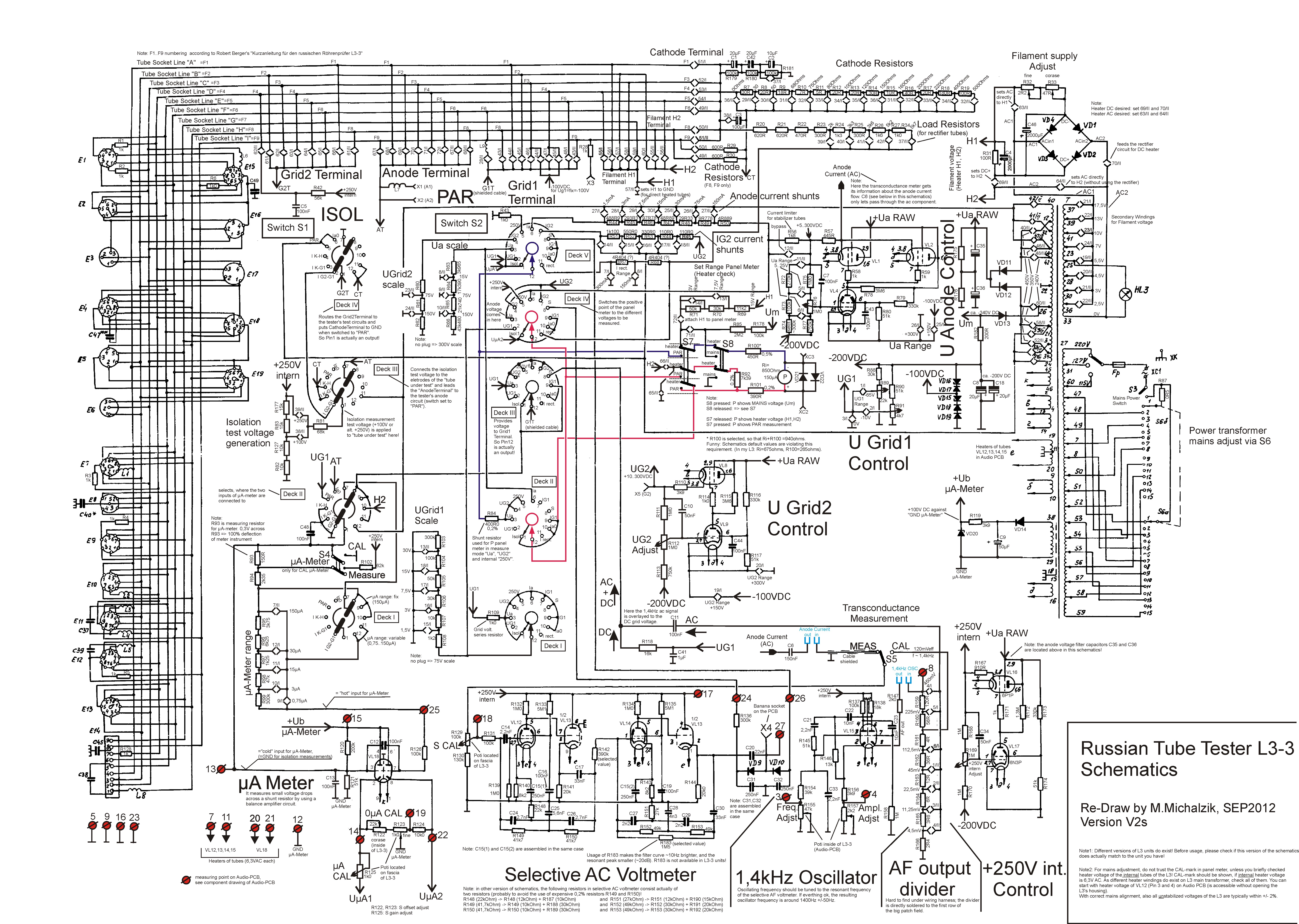
The L3-3 meter is designed to facilitate precise transconductance (Gm) measurements by utilizing a combination of an audio oscillator and a bandwidth filter. The oscillator generates a signal that serves as the foundation for measurements, while the bandwidth filter, known for its sharp response, is critical in filtering out unwanted noise and distortion that could skew results. This includes not only the inherent distortion from the tube itself but also external factors such as power supply hum and environmental interference.
To achieve accurate measurements, it is essential to calibrate the oscillator by connecting it to the bandwidth filter and adjusting the needle to the calibration mark. This step ensures that the sensitivity of the filter is optimized for the base frequency (fo) of the oscillator. The filter is designed to reject higher-order harmonic distortion components, as well as any mains hum frequencies that may interfere with the measurement process. By eliminating these extraneous signals, the transconductance measurement can focus purely on the desired characteristics of the tube under test.
The functionality of the L3-3 meter can be further enhanced through modifications, such as the adjustment of the "test" button, which allows users to toggle between different measurement modes more conveniently. The introduction of a 10-turn potentiometer for the grid voltage (Ug1) simplifies the adjustment process, providing more precise control and reducing the likelihood of temperature drift affecting the readings.
In summary, the L3-3 meter’s design and enhancements significantly improve the accuracy and reliability of transconductance measurements, making it a valuable tool for users requiring high-fidelity testing of tube performance. The combination of a well-calibrated oscillator, a sharp bandwidth filter, and user-friendly modifications ensures that the meter can deliver precise results while minimizing the impact of noise and distortion.The meter has only one scale (0. 150) but this also used for 0. 75 and 0. 30. This is such a pain, and all people use a calculator with it. I made a new meter scale for it, with all ranges. This improves the comfort so much New Meter Scale for your L3-3! Due to many requests, this new meter scale is for sale. This is on an opaque sticker foil. The sticker is from the German company HERMA, who makes professional stickers materials. Remove from your original scale the numbers only, using the tip of a fien cloth, with abrasive cleaning milk, as used in the kitchen. Carefully rub off the original numbers, actually this is really easy to do. Do not rub off the marking triangle called "CAL". Take care, the original scale is 99% water proof. So it may become wet, but you can still damage it when you intensively rub it in wet condition. The original scale is calibrated for YOUR meter, so should not be reprinted or removed. This is why you only have the letters here. Check if the new scale matches your meter before you remove the numbers! This sticker material is professional, and perfect to handle. Apply the sticker at first with some water underneath, so you can move it. Then, with a soft cloth, rub over the sticker gently, thus removing the water underneath. Now Put the scale inside an old book, and lay something very heavy on it. After some hours, it is all dry and nicely glued on, without air or water underneath. Also I added a 6. 3V red line mark, as you need this for most of the tubes anyway. When positioning the scale, make sure the small red line is exactly at 6. 3V. Picture1 - Picture2 Price: 20 Euro + postage + 19% VAT if inside the European community. Sorry for the price, but the stickers are expensive, and it took me two days (!) to get the scales nice, and high resolution.
To see a test result, you need to press the "test" button always. If not pressed it shows the heater. With a careful modification of the "test" button switch, these functions can be reversed, and the user`s comfort increases very much. Read more. I have exchanged the Ug1 (grid) potentiometer for a 10 turns type, and now adjustment is done much easier, and also the temperature drift with the Ug1 is gone.
I would call this a "must" for all L3-3. This is about how you MAY improve the combination Audio Oscillator and the Bandwidth filter. These two cooperate, to do the transconductance measurement. The bandwidth filter is very sharp. It is extremely important to understand that for a precision transconductance (Gm) measurement you need to reject from the measured signal, the TUBE DISTORTION which you always have since tube curves are curves and not straight lines. Also it is pretty clear that an power supply hum may also not be measured. As well as hum radiation from the outside world into the tube. This may seem to logical, but it is the major SIN of many other tube testers. So yes the L3-3 may come sometimes with a little less Gm as you may have expected, but now you know why that is.
So the oscillator produces a signal to begin with, which is a "nice" signal but nothing special. However the Bandwidth filter is special. It is extremely sharp, and it reacts to 1 few Hz changes already. Before a measurement, you need to adjust the oscillator, by connecting it to the bandwidth filter, and set the needle to the calibration mark. By this the sensitivity of the filter is adjusted to the base frequency (fo). So all distortion components of higher order (by Fourier) are f1, f2, f3, etc, these are all rejected.
Also the mix components of the mains hum are rejected. That is 50Hz, 100Hz, but also f0+50Hz, f0+100Hz, f0+150Hz. The whole junk of the oscillator gets filtered out. Now comes the transconductance measurement, by the flip of a switch, and again all junk of the oscillator gets filtered out, but also the distortion products of the tube itself. So you really talk about Gm as pure as can be 🔗 External reference
Related Circuits
This circuit was developed to create a simple network tester that can be operated by a single individual. Commercial units typically require a second person to monitor the remote LEDs, as the transmitters lack the ability to continuously cycle...
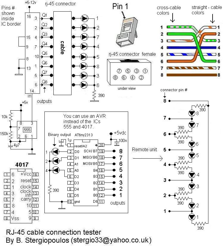
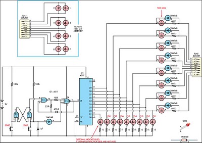
Here is a very simple yet practical circuit designed to check the type of LAN cables (straight or cross) as well as to identify possible faults. The circuit utilizes a unit with 8 outputs, each producing a pulse successively,...
The tester provides an audible indication of the logic level of the signal presented to its input. A logic high is indicated by a high tone, a logic low is indicated by a low tone, and oscillation is indicated...
If you have a servo and you want to test it but do not have a remote control or a dedicated tester, you can create a simple schematic for a servo tester. This circuit is based on a 555...
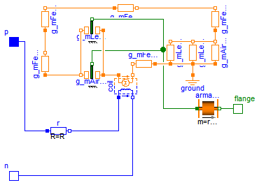
Model SimpleSolenoid is a simple network model of a lifting magnet with a planar armature end face. The parameters include: Resistance R = 10 (Armature coil resistance); Number of turns N = 957; Yoke parameters such as outer yoke...
A fully parametric tube equalizer (EQ) design aims to merge two schematics into one. The goal is to create a tube-based gyrator section with adjustable Q, frequency, and gain while utilizing integrated circuits (ICs) for the input and follower...