
HF SSB CW AM RF Linear amplifier
The described QRP Power Amplifier (PA) is engineered for efficient operation across a wide frequency range, specifically from 300 kHz to 30 MHz, with a gain of approximately 16 dB. The design utilizes RF transformers T1 and T2, which are critical to achieving the amplifier's broad bandwidth. These transformers are constructed using two-hole ferrite balun cores, similar to those found in vintage valve television sets, which enhances their performance characteristics.
The winding process for the transformers involves twisting two lengths of 22 SWG enamelled wire together, which aids in reducing electromagnetic interference and improving coupling efficiency. The configuration requires connecting the end of the "A" winding to the beginning of the "B" winding, establishing a center-tap at this junction, which is essential for balanced operation.
This amplifier is capable of delivering a continuous output power of 4 watts when appropriately heat-sinked, making it robust enough for various applications, including outdoor or field operations. Its design allows for safe operation under load conditions that may otherwise damage typical amplifiers, such as short-circuit or open-circuit situations.
The circuit is versatile, supporting multiple modes of transmission, including Single Sideband (SSB), Continuous Wave (CW), and potentially Amplitude Modulation (AM). The adjustment of RV1 is crucial; it should initially be set to minimum resistance before applying a 12-volt power supply without any input drive. This configuration allows for the adjustment of the total supply current to approximately 250 mA. For applications requiring lower output power, the current can be reduced by decreasing the drive level, thus providing flexibility in operation.
Overall, this QRP Power Amplifier design presents a unique solution for amateur radio enthusiasts seeking a reliable and efficient amplifier for various frequency bands and operational modes.This is a rather unusual QRP Power Amplifier design, with a wide frequency response; within three dB's from 300KHz to 30MHz. Overall gain is in the region of 16dB and the final output power may be well over four watts. The wide bandwidth is a result of the construction of the RF transformers, T1 and T2. These are wound on 2-hole ferrite balun cores as commonly found in the old fashioned valve TV sets (e.g.
Phillips 4322-020-31520). Twist 2 lengths of 22 SWG enamelled wire together and wind as shown. Connect the end of the "A" winding to the start of the "B" winding. Use this junction as the centre-tap of the transformer. This PA will deliver 4 watts continuously (with a suitable heatsink), and may be loaded into a short-circuit or open circuit without causing damage. This makes it almost the ideal PA for outdoor/field use. Above is the full circuit diagram of the RFPA and the coil winding pattern. This PA may be used for for SSB, as well as CW (and AM?). Set RV1 to MINIMUM resistance and apply 12volt power with NO DRIVE. Adjust RV1 for about 250mA DC total supply current. This may be be reduced to a much smaller current if lower output powers (reduced drive) is used. 🔗 External reference
Related Circuits
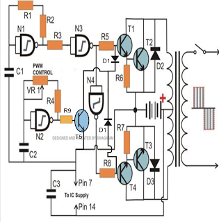
The PWM-controlled modified sine wave inverter circuit presented here utilizes a single 4093 integrated circuit (IC) for its specified functions. This IC consists of four NAND gates, with two configured as oscillators and the other two serving as buffers....

This circuit exhibits an exceptionally fast high-frequency response, as demonstrated by applying a 100 kHz square wave to the input. All graphs were produced using Tina Pro. The circuit's design is optimized for high-frequency applications, showcasing rapid response times that...

It is unlikely that the device was designed to be powered by a 9V battery, as they are not very robust. The battery life is typically under 2 hours when using an alkaline battery. The power requirements of electronic devices...
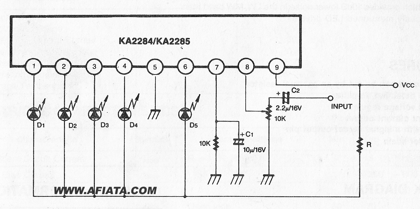
The KA2284 is a monolithic integrated circuit designed for 5-dot LED level meter drives with a built-in rectifying amplifier. It is suitable for both AC and DC level meters, such as VU meters or signal meters. The KA2284 integrated circuit...

This versatile amplifier circuit was designed and submitted by Mr. Seetharaman Subramanian from Chennai. The original concept appeared in Practical Electronics, a UK-based magazine, and the circuit was finalized after extensive field trials and modifications between 1981 and 1986....

This circuit employs the MRF123 TMOS power FET. The MRF134 is a high-gain FET that may exhibit instability at both VHF and UHF frequencies. A 68-ohm input loading resistor has been used to improve stability. This amplifier achieves a...