
FM Booster~Active FM Antenna Amplifier
The FM booster circuit is designed to enhance the reception of FM signals, particularly from stations that are located at a significant distance. The use of the 2SC2570 transistor is crucial as it offers high gain and low noise characteristics, making it suitable for RF amplification applications.
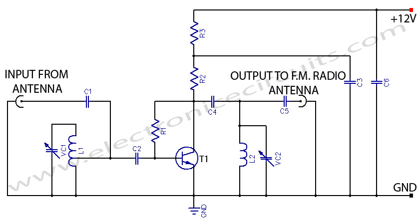
The circuit's architecture employs a common-emitter configuration, which provides a high input impedance and a low output impedance, facilitating efficient signal transfer. The input coil L1 plays a pivotal role in tuning the circuit to the desired frequency, with its four turns allowing for optimal inductance to match the frequency range of FM broadcasts. The slight spacing in the winding of L1 helps in reducing parasitic capacitance, which can adversely affect performance.
The tapping of L1 at the first turn from the ground lead side is a strategic design choice. This configuration allows for better impedance matching and enhances the circuit's selectivity, enabling it to filter out unwanted signals effectively. Coil L2, with its three turns, serves as a secondary inductor that complements L1, further refining the circuit's tuning capabilities.
Overall, this FM booster circuit exemplifies a straightforward yet effective design for improving FM signal reception, making it an essential tool for radio enthusiasts seeking to access distant broadcasts with clarity. Proper assembly and tuning of the coils, along with careful consideration of the transistor's placement and connections, will significantly influence the circuit's performance.This FM booster that can be used to listen to programmes from distant FM stations clearly. The circuit comprises a common-emitter tuned RF preamplifier wired around VHF/UHF transistor 2SC2570. (Only C2570 is annotated on the transistor body. ) Input coil L1 consists of four turns of 20SWG enamelled copper wire (slightly space wound) over 5mm diamet
er former. It is tapped at the first turn from ground lead side. Coil L2 is similar to L1, but has only three turns. 🔗 External reference
Related Circuits
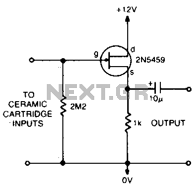
This circuit matches the very high impedance of ceramic cartridges, providing unity gain and low impedance output. By "loading" the cartridge with a 2.2MΩ input resistance, the cartridge characteristics are adjusted to closely compensate for the RIAA recording curve....
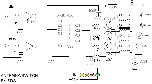
A use has been found for a collection of DIP-style RF relays acquired from a discount electronics shop. These relays are completely sealed and RF shielded, featuring low contact capacitance, making them suitable for VHF frequencies. They operate at...
The following circuit illustrates a 10.7 MHz RF amplifier and filter circuit diagram. Features include significant capacitances of a power MOSFET. The 10.7 MHz RF amplifier and filter circuit is designed to amplify radio frequency signals while simultaneously filtering out...
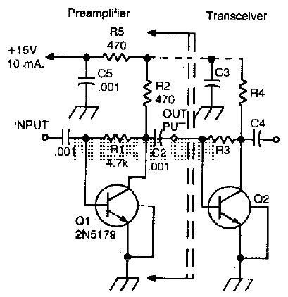
This simple, inexpensive, wideband RF amplifier provides 14 dB gain on two meters without the use of tuned circuits. The RF amplifier described operates within the two-meter band, which typically spans frequencies from 144 to 148 MHz. It is designed...
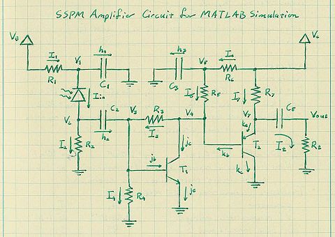
The silicon photomultipliers (SiPM) utilized in the experiment were acquired from Photonique, which also provides analog electronics boards to amplify the signals from the SiPMs. This document addresses the analysis and modeling of the amplifier circuit, along with the...
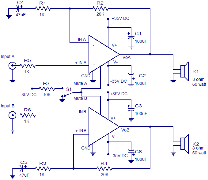
The circuit diagram presented is for a 2 x 60 Watt stereo amplifier utilizing the LM4780 from National Semiconductors. The LM4780 is an excellent audio amplifier integrated circuit capable of delivering 60W RMS power output per channel into 8-ohm...