
VHF FM transmitter
The modulator is a simple circuit which I will post later. Two OP-Amps were used in the prototypes, the first was a MIC amplifier to bring the MIC AF OP up to 500mV RMS. Clamp the AF with a couple of back-to-back diodes (limiter) then the second OP-Amp amplifies the clipped AF to the correct level, (about 1.5v RMS) for 5KHz deviation. Adjust the gain of the first OP-AMP for MIC GAIN and adjust the gain of the second OP-AMP for deviation (with FULL AF).
The output of the driver will supply about 10-20mW to the PA. I didn't use a PA because I lived so close to the repeater (path loss = -109dB). There are hundreds of VHF QRP PA's published in SPRAT, INTERNET, RSGB books, RadCom, and PACKET RADIO so I will leave that to your own ingenuity. A single transistor, such as the 2N3866 will be more than adequate to get up to 250mW, but an additional band-pass tuned circuit should be used between them.
This VHF FM transmitter project is designed for operation within the 2-meter amateur radio band, specifically covering frequencies from 145.00 MHz to 146.00 MHz. The heart of the transmitter is a crystal oscillator utilizing a 44.9333 MHz crystal, which is a common frequency for various radio equipment. The choice of this crystal allows for effective frequency multiplication to achieve the desired VHF output.
The circuit employs a frequency multiplication technique, utilizing a conventional receiver multiplier stage that multiplies the input frequency by three, combined with a 10.7 MHz variable frequency oscillator (VFO). This configuration enables the generation of the necessary VHF signal while maintaining true frequency modulation (FM).
For modulation, the project incorporates two operational amplifiers (OP-Amps). The first OP-Amp acts as a microphone amplifier, boosting the audio frequency (AF) signal to approximately 500 mV RMS. To prevent signal distortion, two back-to-back diodes are used as a limiter, ensuring that the audio signal remains within a manageable range. The second OP-Amp further amplifies the limited AF signal to about 1.5 V RMS, suitable for achieving a frequency deviation of 5 kHz.
The transmitter's output stage is designed to deliver an output power of approximately 10 to 20 mW to the power amplifier (PA). While a PA is not included in the design due to proximity to a repeater, it is advised that users explore existing literature for suitable VHF QRP power amplifier designs. A recommended component for those looking to increase output power is the 2N3866 transistor, which can achieve power levels up to 250 mW. It is essential to include a band-pass tuned circuit between the driver and the PA to ensure efficient operation and minimize unwanted emissions.
The overall design emphasizes simplicity and ease of assembly, making it accessible for enthusiasts looking to explore VHF FM transmission without the complexity of multi-channel tuning.I have had requests to add a VHF FM transmitter, to the QRP collection. This project is a simple transmitter using only one crystal and will cover 145.00 to 146.00 MHz. The crystal is a 44.9333 MHz crystal for 145.500 receive, as used in the Trio (Kenwood) 2200, PYE, Motorolla, Tait equipment, to name but four. The frequency of the crystal is not critical as almost any other xtal for the 2-meter band will function.
No provision has been made to tune the transmitter to different channels, as this transmitter was first used as a single channel "repeater box", leaving my main rig free to be used on other channels. The circuit is given above and simply mixes the output of a (more or less) conventional receiver multiplier (x3) with the output of a 10.7MHz VFO that is modulated with true FM.
Ordinary 1N4001 diodes will function well as varicap diodes, but if true varicap diodes (such as BA102 etc.) are used you will have to reduce the value of the 18pf capacitor coupling D1/D2 to L1. L1 may be a 10.7MHz IF transformer robbed from a domestic receiver, but remove the internal capacitor.
Adjust L1 (10.2 - 11.2 MHz) to cover 145-146 MHz. The modulator is a simple circuit which I will post later. Two OP-Amps were used in the prototypes, the first was a MIC amplifier to bring the MIC AF OP up to 500mV RMS. Clamp the AF with a couple of back-to-back diodes (limiter) then the second OP-Amp amplifies the clipped AF to the correct level, (about 1.5v RMS) for 5KHz deviation.
Adjust the gain of the first OP-AMP for MIC GAIN and adjust the gain of the second OP-AMP for deviation (with FULL AF). The output of the driver will supply about 10-20mW to the PA. I didn't use a PA because I lived so close to the repeater (path loss = -109dB). There are hundreds of VHF QRP PA's published in SPRAT, INTERNET, RSGB books, RadCom, and PACKET RADIO so I will leave that to your own ingenuity.
A single transistor, such as the 2N3866 will be more than adequate to get up to 250mW, but an additional band-pass tuned circuit should be used between them. 🔗 External reference
Related Circuits
The circuit consists of a few components, specifically four, to create a miniature wireless FM microphone. It operates with a stable frequency, achieving a range of over 10 meters with a 1.5V supply and a current consumption of less...
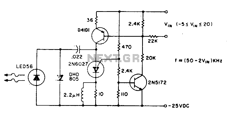
The basic circuit operates at a frequency of 80 kHz, which is constrained by the combination of the PUT (Programmable Unijunction Transistor) capacitors. The maximum modulation frequency achievable is 60 kHz. The pulse repetition rate is directly proportional to...
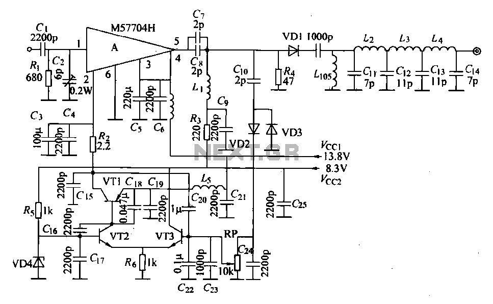
The FM radio transmitter is a high-frequency amplifier circuit that utilizes the Mitsubishi frequency set, specifically the M57704H discharge path. It operates within the frequency range of 457-458 MHz and has a transmission power of 5 watts. As illustrated...

This is the BH1417 USB FM Transmitter featuring a built-in PLL circuit. It converts low-frequency signals into high-frequency signals, allowing any audio device with FM radio capabilities (such as stereo systems, car CD players, MP3 players, and DVD players)...
This project is about an IR-detector (Infra Red) combined with a 100mW 50MHz transmitter. The detector is sensitive to changes in IR-spectrum and is commonly used in burglar alarms. When the detector senses a person/animal/ghost/angry clown, it will transmit...
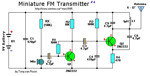
This is a mini FM transmitter designed by Tony van Roon, powered by two transistors. It is straightforward to assemble, and its transmissions can be received on any standard FM radio. The transmitter has an approximate range of 1/4...