
Robot Tutorials
The UART (Universal Asynchronous Receiver/Transmitter) is a crucial component in microcontroller systems that enables serial communication. It operates by converting parallel data from the microcontroller into a serial format suitable for transmission over communication lines. This function is particularly valuable in robotics, where it allows for the integration of various peripherals, including displays, wireless communication modules, and sensors.
The UART operates asynchronously, meaning that it does not require a clock signal for synchronization. Instead, it relies on start and stop bits to delineate the beginning and end of data packets. The standard baud rates (the speed of data transmission) can vary, but common values include 9600, 115200, and others, which can be configured based on the application requirements.
When implementing UART communication, it is essential to consider the voltage levels involved. The transition from RS232 to EIA232F has made UART communication more accessible, as the latter standard allows for lower voltage levels (0V to 5V) that are compatible with modern microcontrollers. The use of an RS232 shifter simplifies the interface between TTL signals from the microcontroller and the EIA232F standard, ensuring reliable communication without the complications of older voltage standards.
In practical applications, the UART interface typically consists of at least two lines: the transmit (Tx) line and the receive (Rx) line. These lines are responsible for sending and receiving data, respectively. Additional control lines, such as RTS (Request to Send) and CTS (Clear to Send), can be included for flow control, enhancing the robustness of the communication link.
The integration of UART in a robotic system not only facilitates communication with a PC for programming and debugging but also allows for real-time data exchange between components. This capability is essential for applications such as sensor data logging, remote control, and telemetry, where timely and accurate data transmission is critical.
In summary, the UART is a versatile and essential component in microcontroller-based systems, providing a straightforward method for serial communication. Understanding its operation, voltage requirements, and integration with modern standards is vital for developing effective robotic applications.The UART, or Universal Asynchronous Receiver / Transmitter, is a feature of your microcontroller useful for communicating serial data (text, numbers, etc. ) to your PC. The device changes incoming parallel information (within the microcontroller/PC) to serial data which can be sent on a communication line.
Adding UART functionality is extremely use ful for robotics. With the UART, you can add an LCD, bootloading, bluetooth wireless, make a datalogger, debug code, test sensors, and much more! Understanding the UART could be complicated, so I filtered out the useless information and present to you only the useful need-to-know details in an easy to understand way.
. . The first half of this tutorial will explain what the UART is, while the second half will give you instructions on how to add UART functionality to your $50 robot. These are the different standards/protocols used from transmitting data. They are incompatible with each other, but if you understand what each is, then you can easily convert them to what you need for your robot.
RS232 is the old standard and is starting to become obsolete. Few if any laptops even have RS232 ports (serial ports) today, with USB becoming the new universal standard for attaching hardware. But since the world has not yet fully swapped over, you may encounter a need to understand this standard.
Back in the day circuits were noisy, lacking filters and robust algorithms, etc. Wiring was also poor, meaning signals became weaker as wiring became longer (relates to resistance of the wire). So to compensate for the signal loss, they used very high voltages. Since a serial signal is basically a square wave, where the wavelengths relate to the bit data transmitted, RS232 was standardized as +/-12V.
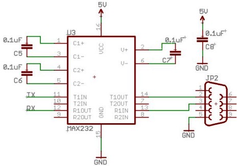
To get both +12V and -12V, the most common method is to use the MAX232 IC (or ICL232 or ST232 - different IC`s that all do the same thing), accompanied with a few capacitors and a DB9 connector. But personally, I feel wiring these up is just a pain. . . here is a schematic if you want to do it yourself (instead of a kit): Today signal transmission systems are much more robust, meaning a +/-12V signal is unnecessary.
The EIA232F standard (introduced in 1997) is basically the same as the RS232 standard, but now it can accept a much more reasonable 0V to 5V signal. Almost all current computers (after 2002) utilize a serial port based on this EIA-232 standard. This is great, because now you no longer need the annoying MAX232 circuit! Instead what you can use is something called the RS232 shifter - a circuit that takes signals from the computer/microcontroller (TTL) and correctly inverts and amplifies the serial signals to the EIA232F standard.
The cheapest RS232 shifter I`ve found is the $7 RS232 Shifter Board Kit from SparkFun. They have schematics of their board posted if you`d rather make your own. And this is the assembled image. Notice that I added some useful wire connectors that did not come with the kit so that I may easily connect it to the headers on my microcontroller board. Also notice how two wires are connected to power/ground, and the other two are for Tx and Rx (I`ll explain this later in the tutorial).
The UART takes bytes of data and transmits the individual bits in a sequential fashion. At the destination, a second UART re-assembles the bits into complete bytes. You really do not need to understand what TTL is, other than that TLL is the signal transmitted and received by your microcontroller UART. This TTL signal is different from what your PC serial/USB port understands, so you would need to convert the signal.
You also do not really need to understand USB, other than that its fast becoming the only method to communicate with your PC using external hardware. To use USB with your robot, you will need an adaptor that converts to USB. You can easily find converters under $20, or you can make your own by using either the FT232RL o 🔗 External reference
Related Circuits
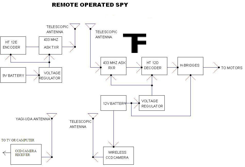
A robot that operates when you send messages through your phone. Your mobile device serves as the remote controller for the robot. This means that if the robot is in London and you are in Mumbai, you can still...
RF technology is an exciting field to incorporate into electronic designs. However, for beginners, constructing reliable RF transmitters and receivers can be challenging. RF (Radio Frequency) technology plays a crucial role in modern communication systems, enabling wireless data transmission over...
One of the motors consistently exhibits hesitation and operates in an unpredictable manner. When tested independently, the motors function correctly without any hesitation. The GPS unit features a Low Voltage TTL serial output on its connector, but a reliable...
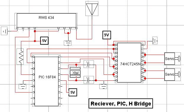
The robot consists of modules controlled by a main controller. The main microcontroller is an 18-pin, 8-bit PIC16F84 Flash microcontroller operating at 4MHz. The microcontroller is programmed in assembly language. The controller is connected via I/O pins to the...
To get enough outputs from the PIC chip, a pair of 74HC164 shift registers was used. These need only two lines from the PIC (data & shift) to produce the twelve signal pulses for the servos. A single bit...
This is a microcontroller hobby project featuring a line-following mobile robot named "Cruddy." The name reflects the somewhat messy structure of the robot. As a first-time builder, the soldering skills may not be fully developed. The chassis was sourced...