
room noise detector

This noise threshold monitoring circuit employs a miniature electret microphone to capture ambient sound. The microphone's output is fed into two operational amplifiers configured in a non-inverting amplifier configuration to increase the signal strength. The gain of the op-amps can be adjusted based on the selected threshold level, allowing for sensitivity tuning to accommodate different environments.
The circuit's design incorporates a potentiometer connected to the op-amps, enabling fine-tuning of the gain to achieve the desired sensitivity level. The output from the op-amps is then connected to a comparator circuit, which compares the amplified microphone signal against reference voltages corresponding to the fixed dB thresholds. When the microphone signal exceeds the set threshold, the comparator activates the LED driver circuit, causing the LED to flash or illuminate steadily.
The use of a switch (SW1) allows the user to select between the various sensitivity settings. In the first position, the circuit is completely powered down to conserve energy. The second through fourth positions activate the circuit and set the sensitivity to the respective thresholds of 85, 70, and 50 dB. The 50 dB threshold is particularly useful for monitoring nighttime noise levels in a bedroom, providing a practical application for improving sleep quality.
Overall, this circuit serves as an effective noise monitoring solution, utilizing simple yet reliable components to provide visual feedback on ambient noise levels. The flashing LED acts as an alert to indicate when noise levels may be too high, promoting a quieter and more conducive sleeping environment.This circuit is intended to signal, through a flashing LED, the exceeding of a fixed threshold in room noise, chosen from three fixed levels, namely 50, 70 & 85 dB. Two Op-amps provide the necessary circuit gain for sounds picked-up by a miniature electret microphone to drive a LED.
With SW1 in the first position the circuit is off. Second, third and fourth positions power the circuit and set the input sensitivity threshold to 85, 70 & 50 dB respectively. The 50 dB setting is provided to monitor the noise in the bedroom at night. If the LED is steady on, or flashes bright often, then your bedroom is inadequate and too noisy for sleep.
🔗 External reference
Related Circuits

A positive-going input charges capacitor C through the IN4148 diode and resistor R. The diode ensures that the silicon-controlled switch (SCS) remains off. A negative-going input provides anode-gate current, which triggers the SCS, allowing capacitor C to discharge through...
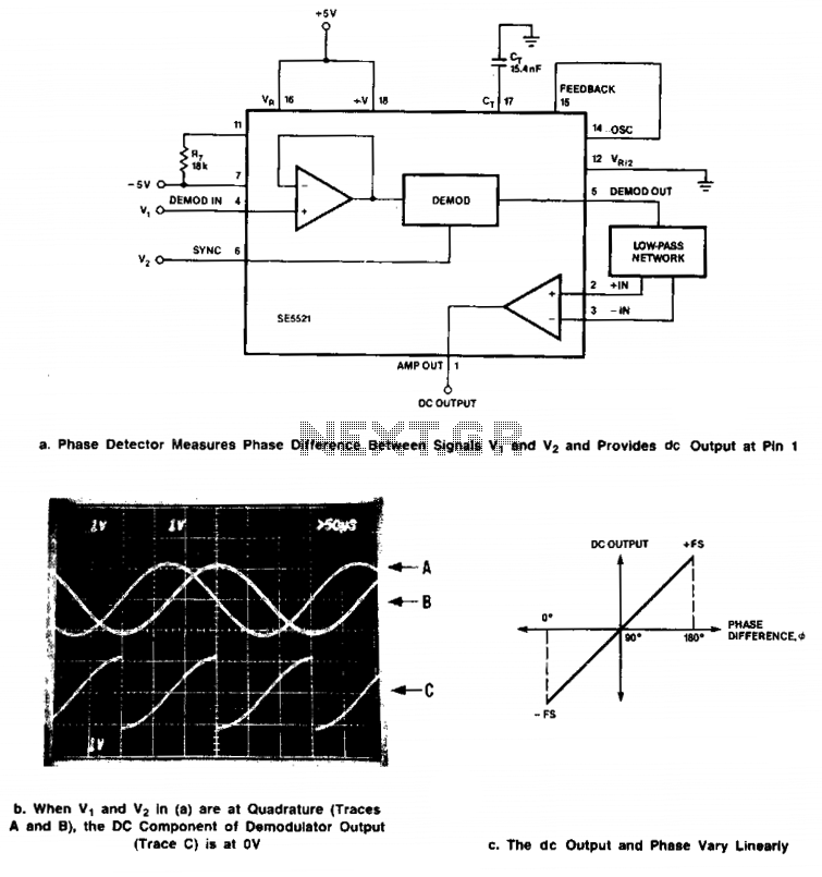
Signals of identical frequency are applied to the sync input (Pin 6) and to the demodulator input (Pin 4). The demodulator operates as a phase detector, with the output DC component being proportional to the phase difference between the...
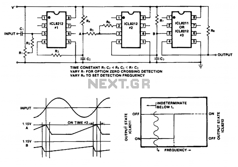
Simple frequency limit detectors providing a GO/NO-GO output for use with varying amplitude input signals may be conveniently implemented with the ICL8211/8212. In the application shown, the first ICL8212 is used as a zero-crossing detector. The output circuit consisting...
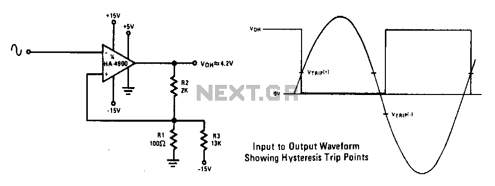
This circuit features a 100 mV hysteresis, suitable for applications demanding rapid output transition times despite slow input signals. The hysteresis loop minimizes false triggering caused by noise on the input. The accompanying waveforms illustrate the trip points established...

The attenuation of ultrasonic pulses transmitted through a test piece indicates the presence and extent of internal defects, such as non-bonds between aluminum cladding and a uranium core. The test piece and transducers are submerged in water to ensure...
.png)
This document describes a simple engineering project circuit for a mobile cell phone detector (sniffer). This compact mobile communication detector can sense the presence of a mobile device, making it suitable for preventing mobile phone usage in private spaces,...