
ROTARY SWITCH DEBOUNCE

Five pots serve for trimming center frequency of each stage andQ of end stages. Article gives step-by-step design and alignment procedures. Use two 10K resistors between V and ground to get V/2 for bias when operating from single supply. -P. A. Stark, Design an Active RTTY Filter, 73 Magazine, Sept. 1977, p 38-43. (View) Triggering is accomplished by turning transistors on, whereas in most similar circuits the transistors are turned off. Trigger pulse merely has to lower point o below ground for fraction of microsecond. Almost any diode and transistor can be used. Speed can be up to 10 Mc with high-speed transistors. Output fall time is fast. -Binary Flip-Flop Tums On, Electronic Circuit Design Handbook, Mactier Pub. Corp. , N. Y. , 1965, p 214. (View) Simple circuit for Signetics NE565 PLL locks to input frequency and tracks it between two values used, to produce corresponding DC shift at output.
Values shown are for 1070-Hz and 1270-Hz FSK signals. Three-stage RC ladder filter removes sum frequency component. Band edge of filter is chosen to be about halfway between maximum keying rate (150 Hz) and twice input frequency (about 2200 Hz). Output is made logic-compatible by connecting voltage comparator to pin 6. - Signetics Analog Data Manual, Signetics, Sunnyvale, CA, 1977, p 845. (View) Cross-coupling of two basic inverters gives low-cost lip-lop using 2N711 germanium pnp mesa switching transistors.
Flip-flop can be set and then reset, or run as Gaunter using combined input. Close regulation is required for -4 v supply. -P. A. Mclnnis, Low-Cost Computer Circuits, Motorola Application Note AN-130, Nov. 1965. (View) Used to protect delicate equipment from sustained high AC line voltage, by disconnecting supply when it exceeds preset level selected by R16. When base-emitter voltage of Tr2 exceeds 7. 5 V, optocoupler switches Tr1 on to provide fast switching action. Output pulse is shaped by IC3 for use in triggering mono IC2. When line falls below preset level, mono reverts to stable state and switches on AC supply again. -F. E. George, A. C. Line Sensor, Wireless World, March 1977, p 42. (View) Seven 567 PLLs sense presence of selected tones from common 100-200 VBMS input line, while 8885 NOR gates perform necessary decoding logic to generate decimal outputs.
Circuit takes advantage of good frequency selectivity provided by lock-and-capture ranges of PLLs, as required for discriminating against many tones. -E. Murthi, Monolithic Phase-Locked Loops-Analogs Do All the Work of Digitals, and Much More, EDN Magazine, Sept.
5, 1977, p 59-64. (View) Output 1 of 322 comparator A1 is high when input signal is above zero and low when input is below zero. Output of comparator A1 is thus square wave in phase with zero crossings of input. When R1, is 22K, input can be up to ±10 V amplitude. A2 is mono MVBR connected to fire when output 1 of A1 goes high (at zero crossings). Resulting negative-going narrow pulses at output 2 are useful for time marks. -W. G. Jung, IC Timer Cook-book, Howard W. Sams, Indianapolis, IN, 1977, p 152. (View) Used for transferring data into storage having heavy capacitive load, such as long connecting wires.
Complementary con figuration, with load in emitter circuit of one transistor, makes stage trigger reliably in fraction of microsecond. -Non-Stalling Flip-Flop for Capacitive Load, Electronic Circuit Design Handbook, Mactier Pub. Corp. , N. Y. , 1965, p 213. (View) Provides full output of 60 V P-P up to 1 MHz Slew rate is 200 V/ s, and small-signal bandwidth is 5 MHz.
Uses fastinput opamp, voltage buffer, and simple compensation technique. C2 is trimme 🔗 External reference
Related Circuits
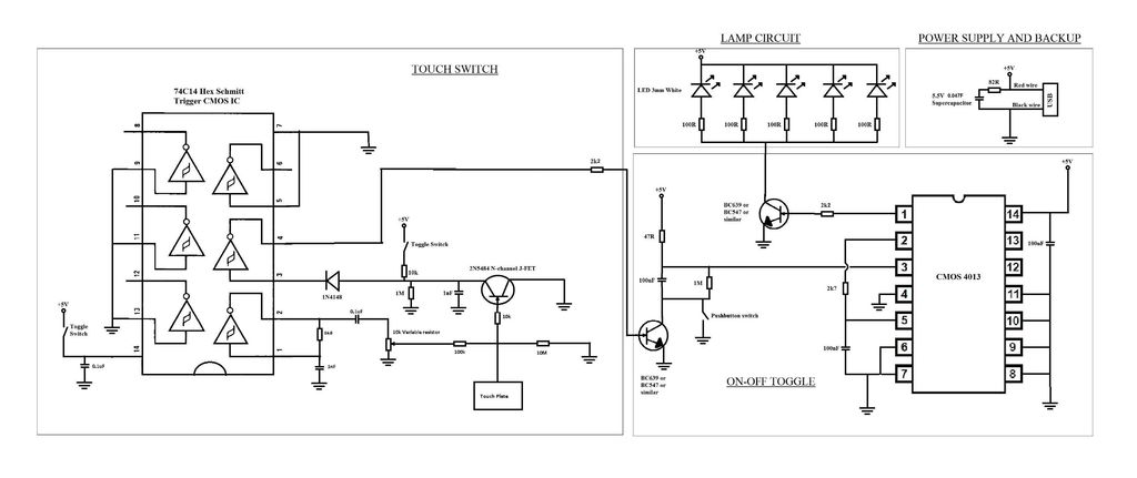
A touch switch for a USB-powered desk lamp is malfunctioning. The circuit diagram, layout, and pictures are provided below. The design incorporates circuits sourced from two websites, specifically the fourth circuit. The output of the touch switch is connected...
This circuit illustrates the TDA1054 tone control stereo preamplifier circuit diagram. Features include the National Semiconductor LM35 integrated circuit, which utilizes semiconductor technology. The TDA1054 is a versatile integrated circuit designed for use in audio applications, particularly in tone control...
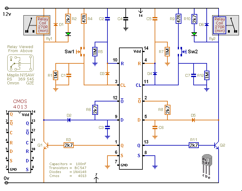
This versatile circuit offers a selection of different switching modes. It can function as two entirely separate toggle switches, with each push button successively energizing and de-energizing its corresponding relay. Alternatively, the two switches can be interconnected with diodes...
A thermally controlled switch operates based on the surrounding temperature without human intervention, except during the construction of the electronic thermostat. This type of switch has numerous practical applications. For instance, it can activate an additional fan when the...
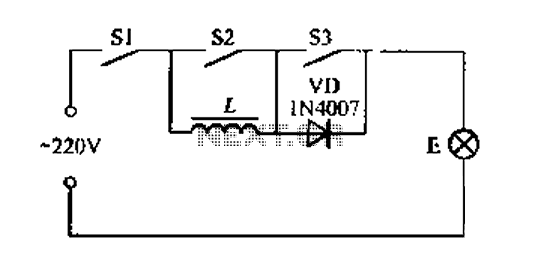
A portable four dimmer switch circuit is illustrated in Figure 8, featuring a four-speed brightness adjustment. When switches S1, S2, and S3 are all closed, the lamp operates at its brightest setting. When S1 and S2 are closed while...
The following touch switch circuit utilizes a CA3240 dual BiMOS operational amplifier to detect small currents flowing between the contact points on a touch plate. The touch switch circuit employs a CA3240 dual BiMOS op-amp, which is known for...