
RS485 Library for Windows and Atmel AVR 8-Bit

The circuit design for the RS-485 communication system includes essential components such as the MAX232 and MAX485 transceivers. The MAX232 is responsible for converting the RS-232 signal levels to TTL compatible levels, which is critical for interfacing with the MAX485. The MAX485 serves as the RS-485 transceiver, facilitating communication over long distances and in noisy environments, which is a significant advantage of RS-485 over other communication protocols.
The physical connections in the circuit involve the TXD and RXD pins of the MAX232 connected to the corresponding RXD and TXD pins of the MAX485. The RTS line, necessary for controlling the direction of data flow in a half-duplex communication system, is also routed through the circuit. This RTS line must be properly configured to ensure that the MAX485 transceiver correctly switches between transmitting and receiving modes.
In terms of software, the implementation on the AVR side leverages the multi-processor communication mode, which allows multiple slaves to be addressed and managed effectively. The protocol's design ensures that the master can communicate with any slave by sending a specific address, while the broadcast capability enhances the system's flexibility.
The choice of baud rate can significantly impact the communication efficacy; therefore, careful consideration should be given to the selected rate to match the system's requirements. The library's support for various AVR models and configurations allows for extensive adaptability in different applications, making it suitable for a wide range of industrial and commercial communication tasks.This project implements a half-duplex, master/slave communications protocol based on RS-485 bus hardware. A Windows PC plays the role of bus-master and several Atmel 8-bit AVRs assume the role of bus-slaves.
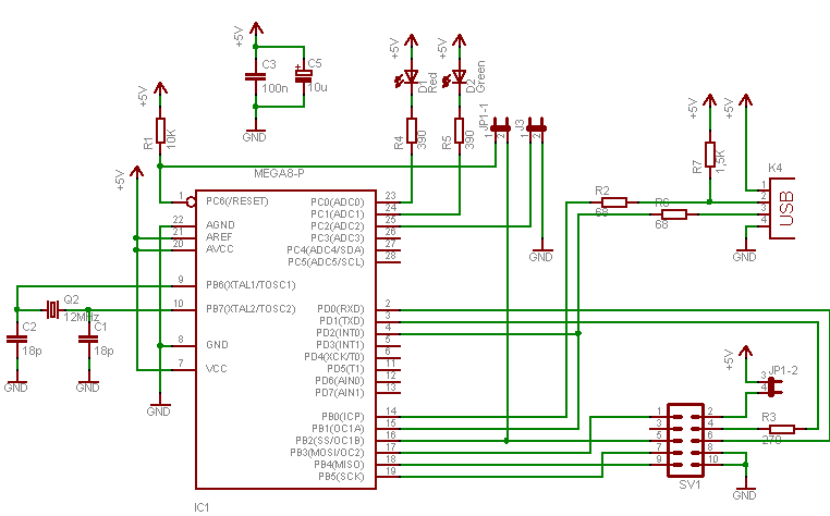
The Windows part is written in C+, the ninth data bit is simulated by the parity bit, the transceiver direction is switched by the RTS line. The AVR part is written in plain C and features the multi-processor communication mode (MPCM). The protocol allows for up to 128 participants. Code and makefile are written for an ATmega8 but should be easily adaptable to any other AVR with UART. The following circuit can be used to convert a PC`s standard serial interface (RS-232) to RS-485 in case you do not have an RS-232 to RS-485 converter already or even an RS-485 PCI card with suitable Windows drivers.
The converter is passive in that it does not involve a microcontroller with two USARTs for translation. The +/-12V RS-232 signals are converted to 0V to +5V (TTL level) by a MAX232 (or similar). The TTL signals are directly feed into a MAX485 (or compatible) RS-485 transceiver. Not only the TXD/RXD lines are taken into account. The RTS line is also brought down to TTL in order to control the direction of the RS-485 transceiver.
The above circuit is a Windows PC`s ticket to the RS-485 world. Later we will see an extension of this circuit. It also contains an ATmega8 for testing RS-485 communication between Windows and AVR. I used this circuit for developing this library. The library implements a basic master/slave bus. There is a single master and multiple slaves. Each slave has its individual/unique address. (The master though has no address. ) All communication is initiated by the master. The slave which was addressed takes the data sent by the master and answers with a response message. If the master sends a message to address 0 then all slaves will read that message but none will respond. Address 0 is the broadcast address. Answering would not be a good idea because all the slaves would answer on the same bus at the same time which is not possible and results in communication error.
The communication happens in a 9N1 style, that is nine data bits, no parity and one stop bit. The ninth bit is set when an address byte is sent by the master. It is cleared in all other cases (master sends data bytes, slave returns response). The baud rate can be defined in the makefile. By default I use 38, 400 baud. This rate can be produced by an AVR driven by the internal 8MHz oscillator with a minimum error rate of 0. 2%. You are free to chose any baud rate with an error rate of 0% if you decide to use a baud crystal (say 14, 7456 MHz).
(A MAX485 has a maximum data rate of 2. 5 Mbps. That means that it is switching faster than your ATMega8. So any baud rate that the ATmega8 delivers can be used. ) The library supports up to 128 participants. How many transceivers can be actually connected to the bus depends on the transceivers. For example MAX485 allows 32 transceivers where MAX487 allows 128. The latest version allows for configuring the port/pin that controls direction of the RS-485 transceiver. PD2 is used as default. Should you want/need to use a different port then use the defines as shown in the following table. (Please be aware that data direction register and port register have to belong to the same port. Furthermore direction bit and pin bit need to designate the same pin. ) It goes without saying that, for single UART AVRs, this library uses the only UART available. For dual UART models UART0 is used by default. Set the define RS485_USE_UART to 1 if you want to use UART1 instead. Otherwise leave it undefined or set it to 0. In theory this library is supposed to support all AVRs with one/two UARTs. But it has been tested with these models only: ATmega8, ATmega162 and ATmega1284P. Request messages are only sent by the master (Windows PC). Slaves do not send requests. They 🔗 External reference
Related Circuits
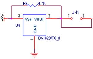
The circuit demonstrates the interfacing of the DS1820 temperature sensor with a microcontroller. The first pin of the sensor is connected to ground (GND), the third pin is connected to the power supply (VCC), and the second pin is...
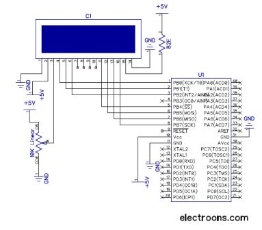
The RW line is the "Read/Write" control line. When RW is low (0), the information on the data bus is being written to the LCD. When RW is high (1), the program is effectively querying (or reading) the LCD....
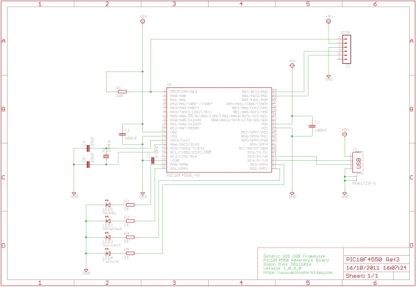
If you have experience with PIC18F microcontrollers and the USB Generic HID standard, you may have noticed the complexity involved in supporting USB on both the PIC18F and the Windows host side. Progressing beyond basic functionalities, such as reading...
To program an AVR microcontroller using a USB port instead of parallel or serial interfaces, USBasp is the most suitable option. A circuit diagram for USBasp is available. The procedure for burning the hex file includes installing avrdude (WinAVR),...
A GPS modem is a device that receives signals from satellites and provides information about latitude, longitude, altitude, and time. GPS navigators are commonly used in mobile devices to track road maps. The GPS modem includes an antenna that...
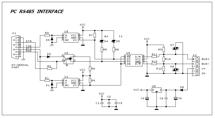
This interface circuit provides electrically isolated RS485 communication interface to the PC serial port. The isolation circuit protects the PC from direct connection to hazardous voltages. More: Figure 1 shows the circuit diagram of RS485 interface. Connector K1 is...