PC RS485 Interface
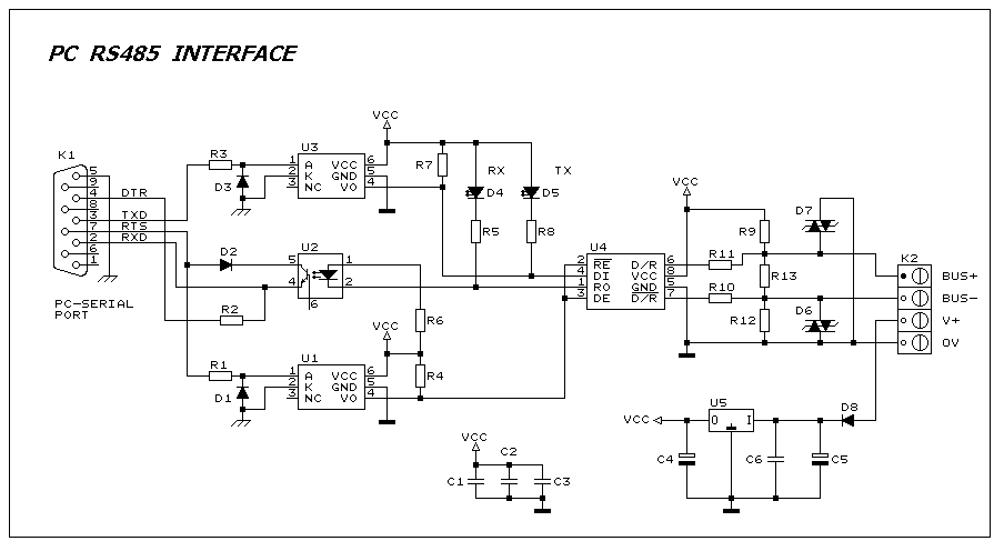
This interface circuit provides electrically isolated RS485 communication interface to the PC serial port. The isolation circuit protects the PC from direct connection to hazardous voltages. More: Figure 1 shows the circuit diagram of RS485 interface. Connector K1 is linked to the serial port of the PC, power to the PC side of the circuit is derived from the signal lines DTR and RTS. Positive supply is derived from RTS and negative supply from the
The RS485 interface circuit is designed to facilitate robust, long-distance communication between a PC and RS485-compatible devices while ensuring electrical isolation to protect sensitive equipment from high voltages. The circuit typically includes a differential driver and receiver, which enable the transmission of data over twisted pair cables, reducing susceptibility to noise and allowing for multiple devices to share the same bus.
Connector K1 is the interface point for the PC's serial port, which connects to the DTR (Data Terminal Ready) and RTS (Request to Send) lines. These lines are used to derive the power supply necessary for the RS485 communication. The RTS line provides a positive voltage supply, while the DTR line is used to establish a negative voltage supply, ensuring that the interface circuit has the necessary operating voltages to function correctly.
The isolation circuit is a critical component of this design, typically implemented using opto-isolators or isolation transformers. This isolation prevents any hazardous voltages present on the RS485 side from reaching the PC, thereby protecting its components and ensuring reliable operation even in electrically noisy environments.
The RS485 transceiver, which is a key component of the circuit, converts the single-ended signals from the PC into differential signals suitable for RS485 communication. This transceiver is capable of driving the twisted pair lines and receiving signals from connected devices. The circuit may also include termination resistors to minimize signal reflections and ensure signal integrity over long distances.
Overall, this RS485 interface circuit is essential for applications requiring reliable communication over extended distances while maintaining electrical safety and protecting the connected devices.This interface circuit provides electrically isolated RS485 communication inteface to the PC serial port the isolation circuit protect the PC from direct connection to hazardous voltages. Figure 1 shows the circuit diagram of RS485 interface. Connector K1 is linked to the serial port of the PC, power to the PC side of the circuit is derived from the signal lines DTR and RTS. Positive supply is derived from RTS and negative supply from the 🔗 External reference

