
salvage dc motor speed control
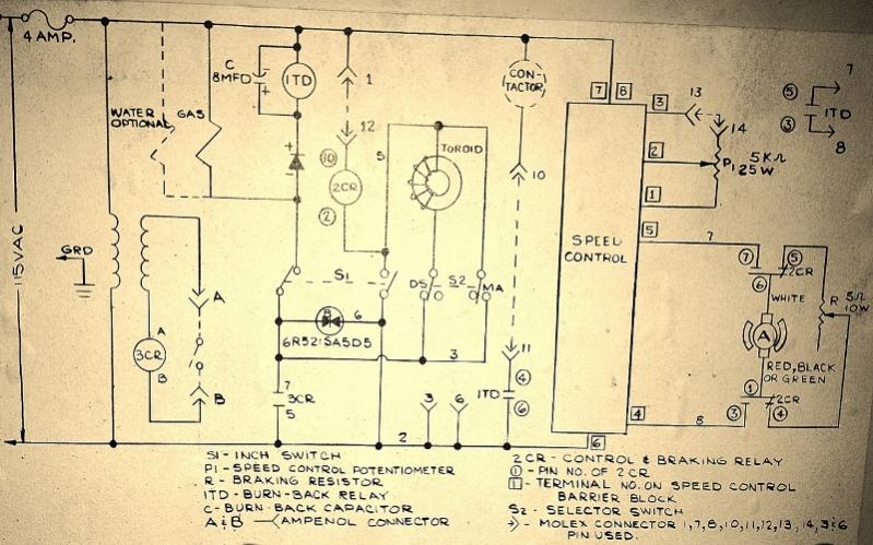
The Chemetron wire feeder is designed for efficient wire feeding in welding applications. The integration of a speed control mechanism from the control box allows for precise regulation of the motor's speed, enhancing operational flexibility and performance.
The proposed circuit should include a variable resistor or a pulse-width modulation (PWM) controller connected to the motor's input terminals. This setup will enable real-time adjustments to the motor speed based on user requirements.
To implement this effectively, the following components are recommended:
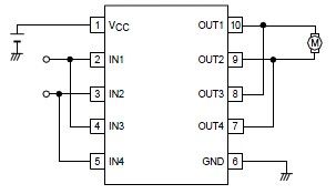
1. **Motor Driver Circuit**: A suitable motor driver circuit should be selected that can handle the voltage and current ratings of the motor. H-bridge configurations are commonly used for bidirectional control.
2. **Speed Control Interface**: The speed control can be achieved using a potentiometer or a PWM signal generator. If using PWM, ensure that the frequency is appropriate for the motor type to prevent overheating and ensure smooth operation.
3. **Power Supply**: A stable power supply must be provided to ensure that the motor receives adequate voltage and current without fluctuations.
4. **Feedback Mechanism**: Incorporating a feedback mechanism, such as an encoder, can help in monitoring the motor speed, allowing for closed-loop control. This setup can enhance precision and responsiveness.
5. **Protection Circuitry**: It is advisable to include protection circuits such as fuses or circuit breakers to prevent damage to the motor and associated components in case of overload or short circuits.
By integrating these components into the existing wire feeder system, enhanced control over the motor speed will be achieved, leading to improved performance and versatility in its applications.I have a Chemetron wirefeeder that I am using the motor and I want to use the speed control out of the control box to control the nice motor it had in .. 🔗 External reference
Related Circuits
The circuit diagram below illustrates a schematic designed to control the speed of a low-power induction motor, commonly found in fans. The schematic for controlling the speed of a low-power induction motor typically incorporates several key components that work together...
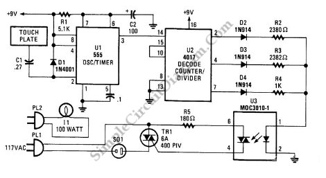
This is a three-mode lamp dimmer circuit with touch control. This circuit can be used to control a lamp in three operation modes: dim, off, and bright. A NE555 timer is utilized in the design. The three-mode lamp dimmer circuit...
This involves controlling servo motors through software programming using the PIC 16C71 microcontroller. The input signals range from 0 to 5V. The circuit utilizes the PIC 16C71 microcontroller, which is an 8-bit device suitable for controlling servo motors. The microcontroller...
A simple forward-reverse motor control driver electronic circuit can be designed using the LB1948M, a two-channel low saturation voltage forward-reverse motor control driver IC. The LB1948M motor driver is suitable for use in 12V system products and can drive...
Radio Control Circuits PDF Manual Download. This document serves as a comprehensive guide to radio control circuits, intended for individuals seeking to understand the principles and applications of radio frequency (RF) technology in controlling various devices. The manual covers fundamental...
This circuit utilizes four IRF510 power FETs driven by a CMOS counter to produce the required two-phase drive quadrature. While integrated circuits (ICs) can perform this function, this method is beneficial for experimenters as it employs widely available components....