
STEPPER MOTOR DRIVER
This circuit design effectively demonstrates the control of a stepper motor using discrete components, specifically four IRF510 power FETs, which are known for their high efficiency and fast switching capabilities. The CMOS counter serves as the primary control unit, generating the two-phase quadrature signals necessary for stepper motor operation.
The four FETs are arranged in a configuration that allows them to alternate the current flow through the motor windings, enabling precise control over the motor's position and speed. The IRF510 FETs are selected for their ability to handle significant power levels, making them suitable for driving the stepper motor without overheating or suffering from performance degradation.
In this application, the CMOS counter generates square wave outputs that are fed to the gates of the FETs. The two-phase output provides the required phase shift that allows the stepper motor to increment its position smoothly. The use of a CMOS counter is advantageous due to its low power consumption and high noise immunity, which enhances the reliability of the circuit.
The stepper motor, sourced from a discarded floppy disk drive, typically consists of multiple coils arranged in phases that correspond to the quadrature signals generated by the CMOS counter. This recycling of components not only reduces costs but also promotes sustainable practices in electronics design.
In summary, this circuit exemplifies an efficient method for controlling a stepper motor using basic electronic components, highlighting the practicality of utilizing available parts for experimentation and learning in the field of electronics.In this circuit, four IRF510 power FETs are driven by a CMOS counter to generate the necessary two-phase drive quadrature. Although ICs are available to do this, this approach is handy for the experimenter because it uses commonly available parts.
The stepper motor was taken from a discarded floppy-disk drive.. 🔗 External reference
Related Circuits
This circuit is 12 volt motors and lights well regulated. The scheme operates with PWM (Pulse Width Modulation). By IC1, a 555 is a square wave generated by a controllable duty cycle. This means that the width of the...
This tutorial explains how to read the content of a microcontroller's flash memory. The source microcontroller reads the memory content and displays it on the LEDs. The content consists of the program stored in the microcontroller's memory. This step...
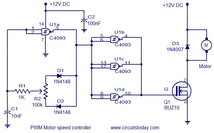
This circuit is designed based on a request from Mr. Vinoth in India. The requirement is for a 12V/5A DC fan motor controller. The circuit utilizes the quad 2-input Schmitt trigger IC CD4093 as its core component. Among the...
The following circuit illustrates the AC Motor Speed Controller Kit - K2636 Circuit Diagram. Features include standard dimmer functionality, utilizing carbon components. The AC Motor Speed Controller Kit - K2636 is designed to regulate the speed of AC motors, making...
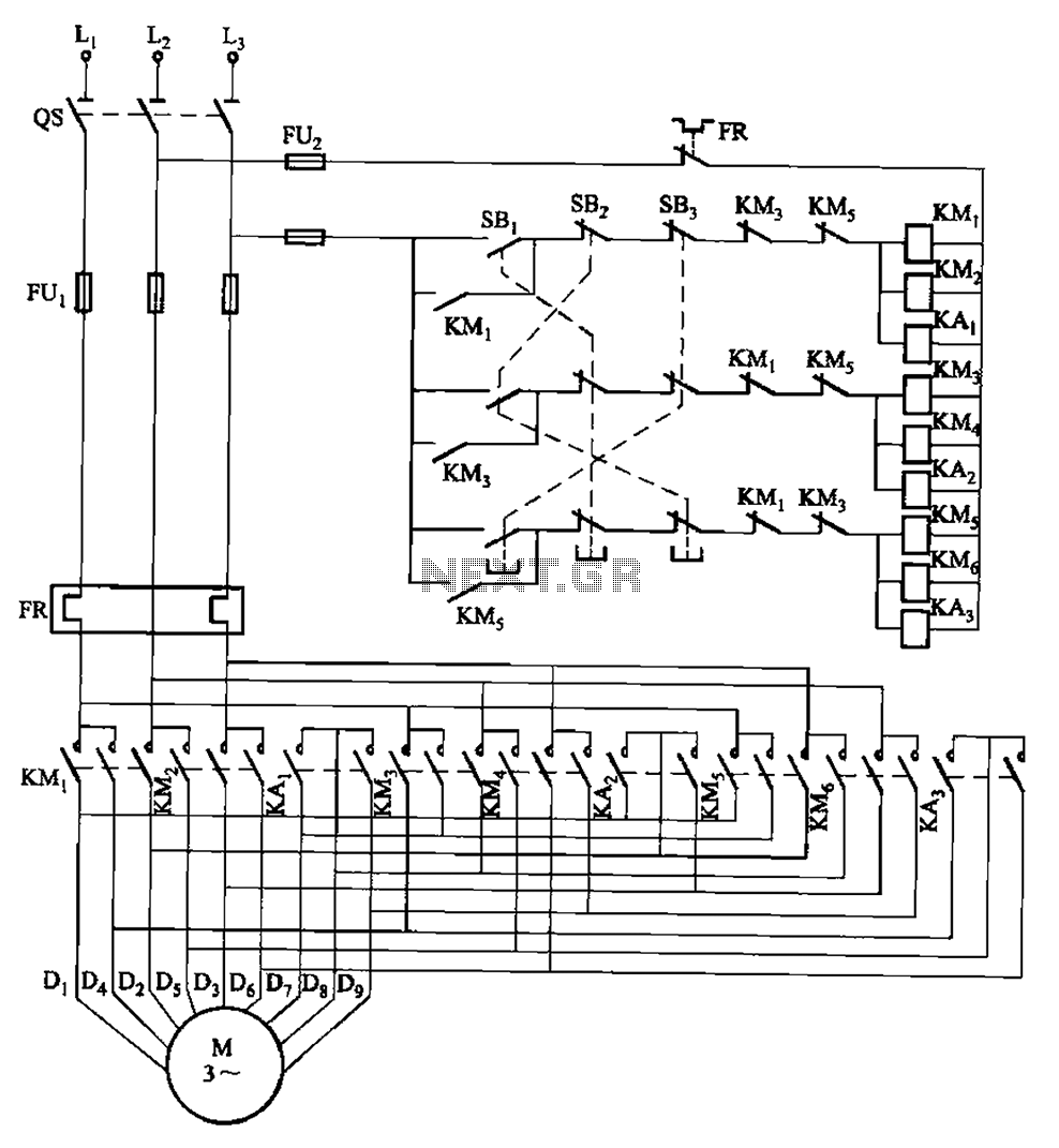
The circuit depicted in Figure 3-115 utilizes contactors and double buttons, allowing for speed conversion without the need to press the stop button. The buttons SBi, SBz, and SB3 correspond to high, medium, and low-speed operation, respectively. This circuit design...
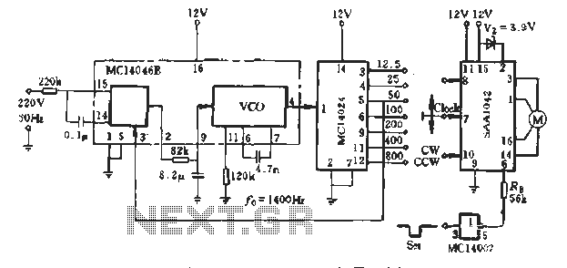
A typical application example is presented, demonstrating the SAA1042 12V stepper motor drive configuration. The phase winding current is set at 200mA. According to RB Figure 5-10, a resistor value of RE = 56kΩ is selected. This resistor is...