
Touch-Controlled Lamp Dimmer
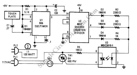
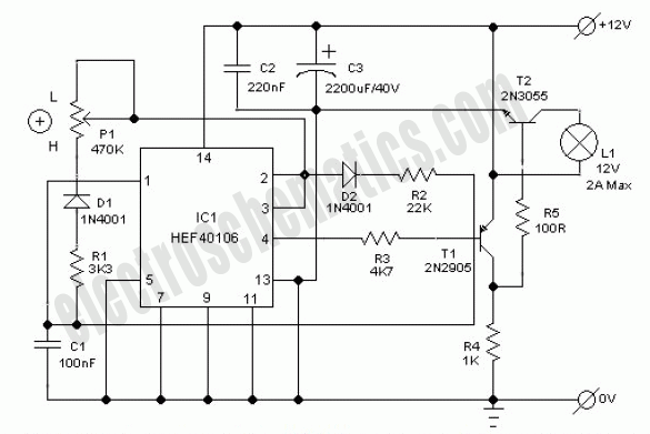
The three-mode lamp dimmer circuit employs a NE555 timer integrated circuit (IC) configured in a monostable or astable mode, depending on the specific design requirements. The touch control feature allows users to switch between the three states—dim, off, and bright—through a simple capacitive touch interface, eliminating the need for mechanical switches.
In the circuit, the NE555 timer generates a pulse width modulation (PWM) signal that is used to control the brightness of the lamp. The duty cycle of this PWM signal can be adjusted based on the touch input, allowing for smooth transitions between the different brightness levels.
The touch sensor can be implemented using a capacitive touch pad connected to the input of the NE555 timer. When the pad is touched, it triggers the timer to change its output state. The output from the NE555 is then fed into a transistor or a triac, which acts as a switch to control the power delivered to the lamp.
Additional components may include resistors and capacitors that set the time constants for the NE555 timer, ensuring that the response to touch inputs is both quick and reliable. A diode may also be included for flyback protection if an inductive load is used.
Overall, this circuit design provides an efficient and user-friendly method for controlling lamp brightness, enhancing both functionality and aesthetics in various lighting applications.This is a three-modes lamp dimmer circuit with touch control. This circuit can be used to control a lamp in 3 operation modes: dim, off, and bright. A NE555 . 🔗 External reference
Related Circuits
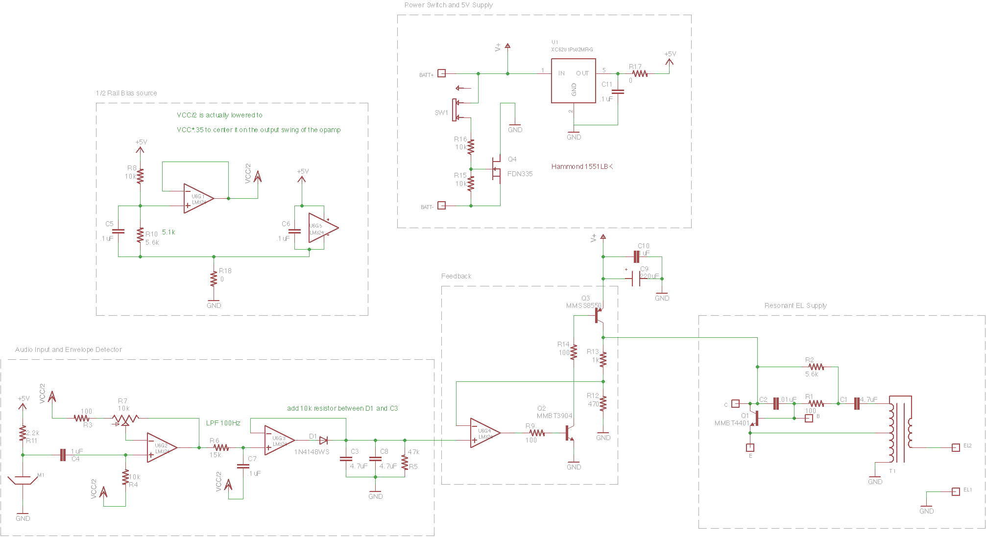
Eight months and eighteen days ago, on March 25, a request was received via email for a commissioned piece of electronic clothing similar to a DJ jacket for a musical performer to wear on stage. After some consideration, the...
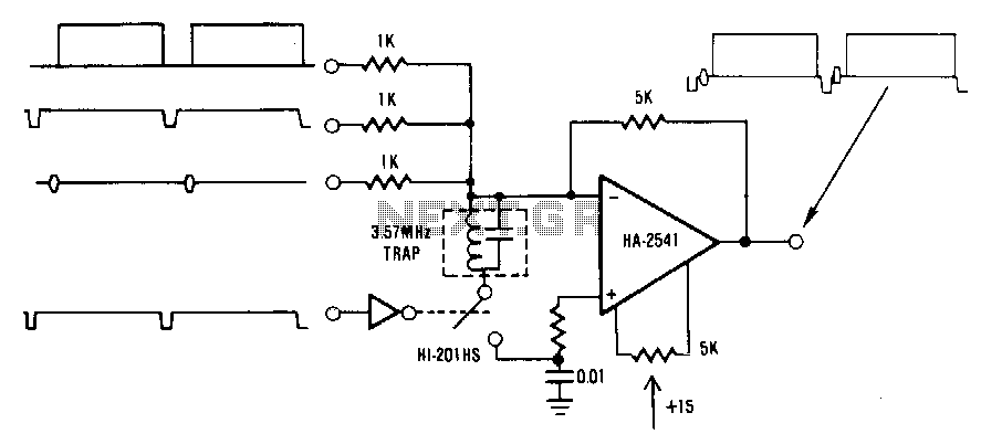
This circuit is a conventional summing amplifier configuration that incorporates a de-clamping circuit. The operation is straightforward; each component—synchronization, color burst, picture information, etc.—of the composite video signal is connected to its respective input terminal of the amplifier. These...
This circuit is a simple manual analog light control desk that outputs standard 0-10V control signals suitable for controlling professional light dimmers and other lighting equipment. The controller's output is a steady DC voltage that varies between 0 and...
This electronic lighting dimmer circuit is designed to control the brightness of incandescent lamps, but it is not suitable for fluorescent lamps. It operates with both 110V and 220V AC power sources. The circuit is connected in series with...
Here is a circuit diagram for adjusting the brightness of a light bulb. The second battery is utilized to power the circuit. This circuit can be used to modify the brightness of images during close-up photography with a digital...
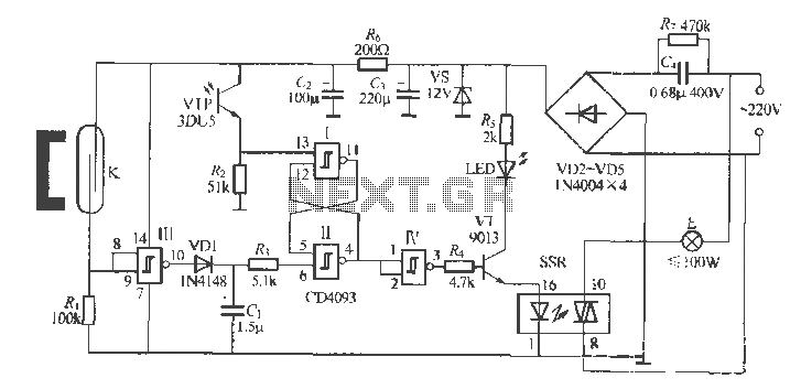
The circuit utilizes multiple integrated circuits to form an automatic lighting device that is activated by door and window sensors. It includes CD4093 digital integrated circuits, a relay, and a power supply circuit. The system typically remains closed when...
Warning: include(partials/cookie-banner.php): Failed to open stream: Permission denied in /var/www/html/nextgr/view-circuit.php on line 713
Warning: include(): Failed opening 'partials/cookie-banner.php' for inclusion (include_path='.:/usr/share/php') in /var/www/html/nextgr/view-circuit.php on line 713