
Sawtooth Wave Generator
The sawtooth wave generator circuit consists of two main components: the NE555 timer and the uA741 operational amplifier. The NE555 timer is configured in astable mode to generate a square wave output. The frequency of this square wave can be adjusted by varying the resistors and capacitor connected to the timer. The output of the NE555 timer switches between high and low states, producing a square wave that oscillates between the supply voltage levels.
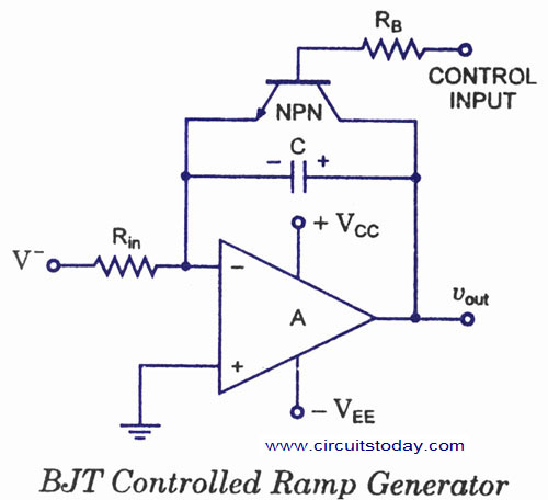
This square wave output is then fed into the uA741 operational amplifier, which is configured as an integrator. The integrator takes the square wave input and produces a sawtooth waveform as its output. The integration process involves charging and discharging a capacitor in response to the square wave, resulting in a linear ramp-up of voltage followed by a sudden drop, which characterizes the sawtooth waveform.
The circuit typically includes a resistor and capacitor connected to the inverting input of the uA741. The feedback loop is critical for maintaining the integration process and ensuring that the output waveform has the desired characteristics. The output frequency and amplitude of the sawtooth wave can be adjusted by modifying the values of the components in both the NE555 and uA741 sections.
In practice, this sawtooth wave generator can be used in various applications, including signal processing, waveform generation for audio applications, and as a timing source in other electronic circuits. The combination of the NE555 timer and uA741 operational amplifier provides a reliable and straightforward method for generating sawtooth waveforms in a compact circuit design.Sawtooth wave generator using NE555 and opamp uA741. NE555 is wired as square wave generator and opamp is wired as integrator.Circuit diagra, and working theory.. 🔗 External reference
Related Circuits

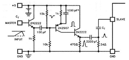
By utilizing a 556 dual timer, with IC1A functioning as a waveshaper and IC1B as a pulse generator, a pulse width range of 10:1 can be achieved. This circuit can be triggered using a sine wave. The circuit operates on...
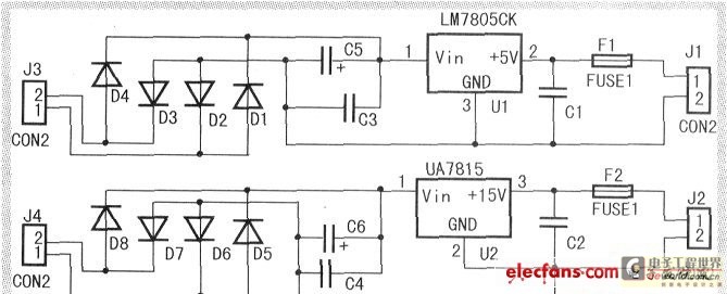
When the input voltage is between 198-242V, the average load current should be maintained at 0.5-1A, and the output voltage must remain at 15V with an error margin of less than 5%. The design and measurement of the stabilized...
This simple circuit generates a good and stable 1V peak-to-peak square wave at 100Hz, 1KHz and 10KHz using a single 1.5V cell as power supply. An useful feature of this circuit is that frequency changes can be obtained by...
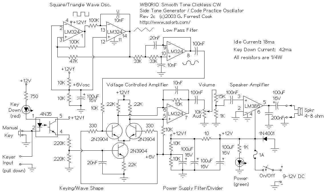
This circuit is about as good as it gets for generating morse code tones. It may be used as a code practice oscillator, a tone generator for a keyer, a sidetone oscillator for a CW transmitter or an audio...
The UC3842, UC3843, UC3844, and UC3845 series of oscillators can generate synchronization pulses without requiring numerous external components. The following circuit illustrates the Sync Pulse Generator Circuit Diagram for the UC3842/3/4/5. This sync pulse circuitry is capable of operating...
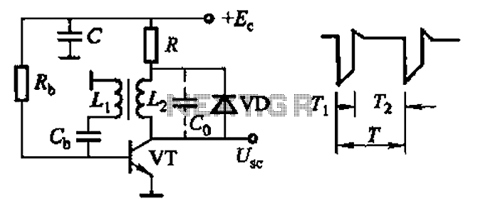
Common non-sinusoidal oscillator circuit, waveform and frequency formula - sawtooth oscillator - use blocking oscillator The sawtooth oscillator is a type of non-sinusoidal oscillator that generates a waveform characterized by a linear rise in voltage followed by a rapid drop....