
Sine wave oscillator

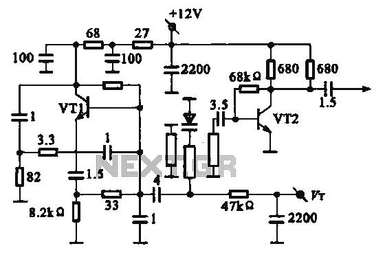
The sine wave oscillator circuit operates by utilizing a combination of capacitors and resistors to generate a stable sine wave output. The frequency of oscillation is primarily determined by the values of the capacitors and resistors in the circuit. In this particular design, the three capacitors (C1, C2, and C3) are configured in such a way that their total capacitance influences the oscillation frequency.
To calculate the frequency of oscillation, the formula typically used is:
\[ f = \frac{1}{2\pi RC} \]
where \( f \) is the frequency in hertz, \( R \) is the resistance in ohms, and \( C \) is the total capacitance in farads. In this circuit, the total capacitance of 100 pF is achieved by combining C1, C2, and C3 in parallel. The ability to modify the values of these capacitors allows for fine-tuning of the output frequency, ranging from a minimum of 5 Hz to a maximum of 5 kHz.
For practical implementation, the resistors used in conjunction with the capacitors must also be selected carefully to ensure stability and linearity of the output waveform. The circuit may include additional components such as operational amplifiers to buffer the output signal, ensuring that the sine wave is not distorted by the load connected to it.
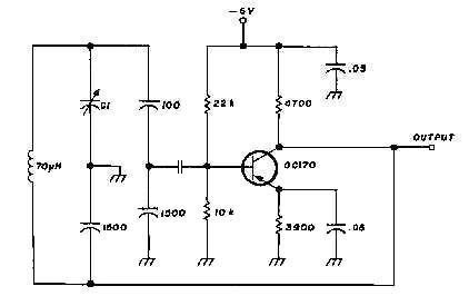
Overall, the sine wave oscillator circuit is useful in various applications, including signal generation for testing, audio applications, and modulation schemes in communication systems. Proper layout and component selection are critical to achieving the desired performance characteristics of the oscillator.This scheme is sine wave oscillator, with frequency from 5 Hertz up to 5 KHZ. Capasitor C1, C2, C3 altogether valuable 100pF, yielded frequency 5 KHZ. To get other frequency magnitude of we ready to change value at C1, C2 and C3, like under this. 🔗 External reference
Related Circuits
This Hartley oscillator was constructed using a single 45 tube and is based on a design published in a 1932 QST article by George Grammer. The initial circuit experienced performance issues due to weak 45 tubes, necessitating a very...
The Vackar configuration is recognized as one of the most stable VFO oscillators available. However, its usage is limited due to the NIH (not-invented-here) syndrome. This oscillator offers a frequency tuning range exceeding 2.5, a feature not typically found...
A piezo disk is being driven at a frequency of 100 Hz or lower, with the output from the signal generator limited to 10 V. The goal is to amplify this output to 50 or even 100 Volts. To achieve...
A Wien bridge oscillator generates sine waves with a very low distortion level. It produces zero phase shift at a single frequency (f = Vx t RC), which is the oscillation frequency. Stable oscillation can only occur if the...
The schematic diagram presented is of a twin "T" phase shift oscillator, an audio oscillator. This oscillator derives its name from the phase shift network formed by resistors R3, R4, and capacitors C1, C2, and C3. This network shifts...
The local oscillator operates at frequencies of 1 GHz or higher, utilizing a common collector circuit, which makes it challenging to generate low-frequency self-oscillation. Typically, the local oscillator signal is passed through a buffer amplifier stage before being applied...