
Single-chip audio power amplifier circuit
The OPA541 power amplifier is designed to deliver high efficiency and low distortion for audio applications. With a maximum supply voltage of 40V, it can effectively amplify audio signals while maintaining fidelity. The continuous output current capability of 5A makes it suitable for driving various loads, including speakers with low impedance. The external resistors R6 and R7 play a crucial role in current limiting, ensuring that the amplifier operates within safe parameters to prevent damage from overcurrent conditions.
The circuit configuration allows for flexibility in adjusting the output current, enhancing the protection of the load and the amplifier itself. The calculated current threshold resistor Rc is essential for fine-tuning the performance of the amplifier, allowing for customization according to specific application requirements. The low total harmonic distortion (THD) of less than 0.5% indicates that the amplifier can reproduce audio signals with high accuracy, making it ideal for high-fidelity audio applications.
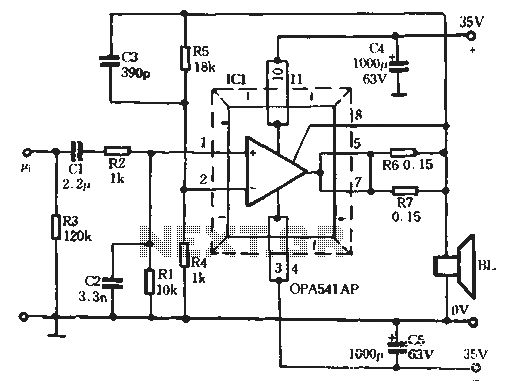
The bandwidth specifications, defined by the components C3, R2, and C2, ensure that the amplifier can effectively handle a wide range of audio frequencies, while the low-end cutoff frequency established by R1 and C1 ensures that low-frequency signals are adequately amplified without significant attenuation. This design allows the OPA541 to excel in various audio amplification scenarios, providing robust performance and reliability.Burr-Brown OPA541 chip is produced by a power amplifier, which can by a maximum of 40V power supply electricity to produce the maximum continuous output current of 5A. Via an external resistor, adjust the size of the output current to protect the discharge amplifier and the load, so that the normal work © OPA541 has two packages, one is plastic ß feet, the other is a 3 TO sealed package. OPA541 is a better performance of the power amplifier. Circuit shown in Figure 5-106, the circuit in the input audio signal level value of 1. 3V; which, when the symmetrical earth 35v power supply, it is possible to provide a load of about 80 to 60W mouth this time, through parallel resistance R6, R7 limits the output current value (max 8.
5A), but also safe driving 4n of the load, and thus obtain the maximum driving power. However, R 6 and R7 set the amplifier to be taken to ensure safety to give short circuit protection make the amplifier 6 in its area of work safety, it requires current threshold is 1. 8A. Determine current threshold resistor Rc, can be calculated following formula: Rci = (0.813 / Laha) -0.02 (N) low-distortion of the amplifier, THD less than 0.5% O lC quiescent current of only ZOmA, bandwidth used by C3 decision, approximately 22kHz, the input filter R2, C2 for reducing IMD (intermodulation distortion internal), and reduce the bandwidth, the actual bandwidth reduced 16.
6kHz; low end cutoff frequency of the R 1, C 1 decides for 6. 6Hz. / P SE "). Change (function () {J SRPPShunt Regulated Push Pull cSRPP " f" o c 6F2 " beta " SRPP " f " b " beta " R6, R7 m 2-10 b cSRPP Two Pass J F3mA " beta " I, o F2.5mAc
Related Circuits
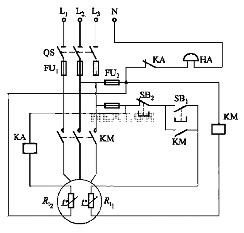
The circuit illustrated in Figure 4-2 employs two thermal resistors. One, designated as Rc, functions as overload protection, while the other, labeled Rt, serves as an alarm. The circuit in question integrates two thermal resistors to monitor temperature changes and...
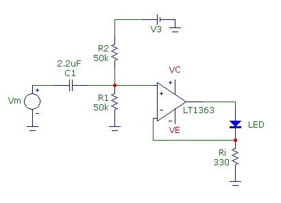
Common Light Emitting Diodes (LEDs) require a direct current (DC) forward bias of 10 to 20 mA for optimal performance. The maximum allowable DC current typically ranges from 30 to 50 mA. The emitted light color, or wavelength, from...
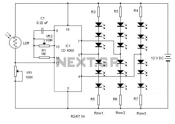
This simple circuit can create an 18 LED flasher to decorate a Christmas tree. The white, blue, and red LEDs flash at different rates to provide a colorful display. It is a light-sensitive circuit, automatically activating in the evening...
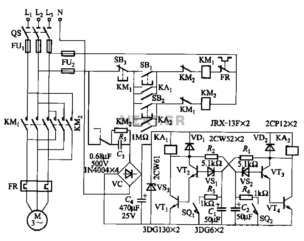
The circuit illustrated in Figure 3-72 employs a deformable bistable reversing motor control mechanism that automatically initiates and halts operation during a user-defined time delay. This feature is designed to safeguard the motor from potential impacts during the reversing...
The 555 timer on the right is configured as an alarm sound generator, while the second 555 timer on the left functions as a 1 Hz astable multivibrator. The output from the left timer modulates the frequency of the...
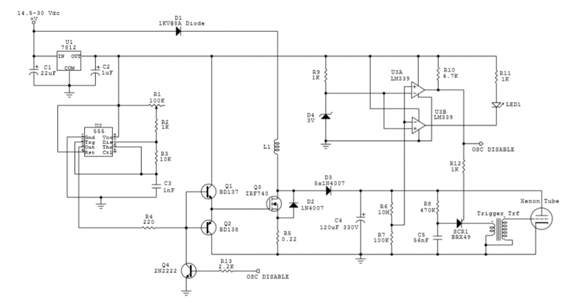
The circuit utilizes an IRF740 MOSFET, which has a maximum drain-source voltage (V_DS) rating of 400V. The avalanche voltage is calculated to be approximately 3520V, indicating that up to about 500V of inductive kickback voltage can develop in the...
Warning: include(partials/cookie-banner.php): Failed to open stream: Permission denied in /var/www/html/nextgr/view-circuit.php on line 713
Warning: include(): Failed opening 'partials/cookie-banner.php' for inclusion (include_path='.:/usr/share/php') in /var/www/html/nextgr/view-circuit.php on line 713