
Transistor inverter circuit 6
The described inverter circuits leverage various transistor types and configurations to achieve efficient voltage conversion from low DC levels to high AC outputs. The use of components such as the CMOS 4047 and SCRs enhances the circuit's functionality, allowing for frequency modulation and improved performance. The incorporation of toroidal transformers further optimizes efficiency by reducing magnetic losses, which is critical in high-frequency applications. The circuits are designed to be user-friendly, enabling hobbyists and engineers to construct them with minimal resources. Safety considerations, such as the inclusion of fuses and protective elements, are essential to prevent damage under adverse conditions. Overall, these inverter designs exemplify practical solutions for converting DC power to AC, suitable for various applications including lighting and general power supply needs.This is transistor inverter circuit diagram 100watt it sizes are easy circuit. Because of use the all transistor, have no the integrated circuit. It performs to modify from battery 12V be 220V 50Hz signal square wave. By the circuit works with transistor BC558 x 2pcs and RC assemble the circuit produces 100HZ frequency from that time. There is the transistor BC558 2 again, build the circuit divides by 2 times frequency be left 50Hz frequencies from that time. There is the transistor BD139 and 2N3055 each other be Darlington for drive AC transformer 12V CT 12V : 220V, enhance ac voltage 12V from be 220V 50HZ fully be usable next.
The detail is other see in inverter circuit diagram. This converter has a central component, the CMOS 4047, and converts a 12V DC voltage to 220V AC voltage. 4047 is utilised as a astable multivibrator. At pin 10 and 11 we find a rectangular symmetrically signal which is amplified by tow Darlington transistors T1 and T2 and finally reaches the secondary coil of a transformer network (2 x 10V/60VA).
Primary coil terminals voltage is 220 alternative voltage. To obtain a better performance use a toroidal core transformer with reduced losses. With P1 the output frequency can be regulated between certain limits (50 400Hz). This be Mini Power Inverter, by use SCR be main part electronics, perform Oscillator Generator 400Hz give Output 300V by use Voltage Input 12V Current 0. 8A. The only drawback with this circuit is that it might latch in the conducting state if the load is too heavy or if there is a short at the output, this requires some kind of protection, on the input line, in the form of a fuse or similar.
The transformer used is a 10W mains type with 6V+6V windings on the SCR side and a 110V+110V windings, in series, at the output. Efficiency is 50% and the ideal load is equivalent to a 22k resistor, 5W. The output waveform is vaguely sinusoidal at a frequency of 400Hz. This is Simple High Power inverter by 2N3055 circuit. It use power transistor 2N3055 x 4 pcs. Assemble be Oscillator muti vibrator Drive Transformer output 110V by Input battery 12V, Because of this circuit.
Design be simple then not tall effective, but may advantage with friends at like the circuit is simple, at good effective. For other detail, friends sees in the circuit please yes. I seeks a picture inverter circuit for experience build mini inverter project. Accidentally meet Simple Mosfet AC Power Inverter Circuit. Think should advantage with friends from the circuit uses integrated digital circuit number CD4001 for Pulse Oscillator Generator.
Give power mosfet driver Transformer get Voltage output 110V or 220V from input 12 Volt (Battery 12V). For VR1 give for fine the frequency oscillator output. The other detail see in the circuit by have, Image source: This be basic AC inverter Circuit. Convenient for the initiator who have to is extremely fond of something experience. Because of use IC 555 highly popular, perform produce the frequency, then enlarge with transistor NPN and PNP number TIP41 and TIP42 drive the coil transformer.
Get by can pay Voltage output about 120V to 230V at frequency 50Hz. By have R4 perform control the frequency and should use. Voltage supply about 5V to 15V the detail sees in circuit picture sir. This is the typical circuit from a scanner that drives the flourescent lamp. There is also usually a 2KV capacitor in series with the secondary of the transformer to limit current, etc. They can be used as a general high voltage source for all kinds of things. This is a low-cost project for 20 or 40 watt fluorescent tubes. However the most efficient is to use a 40 watt tube (or two 20 watt tubes in series). It`s a circuit you can put together from junk box components or build from a kit. It`s very simple to build and requires no printed circuit board. This is an electronic choke for a Conventional Fluorescent Lamp. This was an application note of M 🔗 External reference
Related Circuits
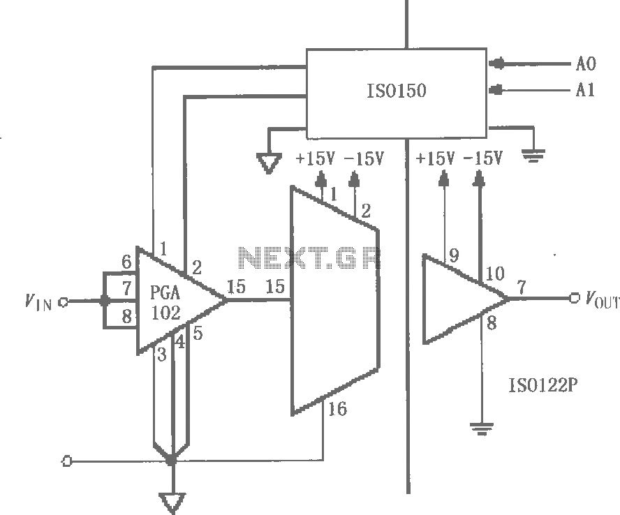
The circuit features grounds ISO122/124 and PGA102, with ISO150 forming a gain programmable channel isolation circuit. The input signal VIN is amplified by the instrumentation amplifier PGA102 to ISO122P, which then outputs VOUT from the isolation amplifier ISO102P. Two...
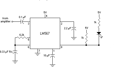
This is an FSK modulation circuit composed of the 74LS74. The FSK modulation circuit does not include a phase-locked loop (PLL) or a high-Q bandpass filter, eliminating the need for tuning adjustments in the high-frequency modulation circuit. The two...
Adrian Bontenbal has provided updated notes from his experiments in recreating Clara Rockmore's theremin. Bob Moog shared his hand-drawn schematic for Clara's instrument over a decade ago. Adrian started with that schematic to build his own Rockmore theremin. During...

This circuit is beneficial for amateur radio operations in VHF and UHF frequencies, where a mast-mounted antenna preamplifier is employed for reception. The kit manages the transmit-receive (T-R) switching and relay sequencing to prevent high RF levels from being...
The text of the Arduino reference is licensed under a Creative Commons Attribution-ShareAlike 3.0 License. Code samples in the reference are released into the public domain. The Arduino platform is an open-source electronics prototyping environment that enables users to create...
Commercial FM demodulation occurs at an intermediate frequency (IF) of 10.7 MHz. With a frequency deviation of ±75 kHz, the deviation of the IF carrier is approximately ±0.7%. This deviation allows for the conversion of FM to AM or...
Warning: include(partials/cookie-banner.php): Failed to open stream: Permission denied in /var/www/html/nextgr/view-circuit.php on line 713
Warning: include(): Failed opening 'partials/cookie-banner.php' for inclusion (include_path='.:/usr/share/php') in /var/www/html/nextgr/view-circuit.php on line 713