
Inexpensive Vhf/Uhf Diode Rf Switch
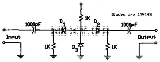
The described circuit is a simple yet effective RF switch that leverages the characteristics of the IN4148 diodes to control signal paths based on the applied bias voltage. The use of these diodes is advantageous due to their low cost and availability, making the circuit suitable for budget-sensitive applications.
In the circuit, the insertion loss of approximately 1.5 dB indicates that the switch maintains a relatively low level of signal attenuation, which is crucial for RF applications where signal integrity is paramount. The isolation of 30 to 50 dB achieved in the negative bias state means that when one path is activated (D3 conducting), the other paths (D1 and D2) are effectively blocked, preventing signal leakage and ensuring that the output is clean and unaffected by other channels.
The switching mechanism relies on the biasing of the diodes. In the negative bias condition, D3 is forward-biased, allowing current to flow through it while cutting off D1 and D2. Conversely, applying a positive bias forward-biases D1 and D2, allowing them to conduct while D3 is turned off. This dual-state operation enables the circuit to switch between different signal paths effectively, making it versatile for various RF switching applications.
The circuit design can be further enhanced by incorporating additional components such as resistors to limit current through the diodes, capacitors for filtering, or inductors for impedance matching, depending on the specific requirements of the application. Overall, this low-cost RF switch circuit is an efficient solution for applications needing reliable signal routing with minimal insertion loss and high isolation. This circuit uses low-cost IN4148 diodes and exhibits about 1.5 dB insertion loss from 10 to 1000 MHz w ith a few volts of negative bias. D3 conducts and D1/D2 are cut off, which results in 30 to 50 dB isolation. When a few volts of positive bias are applied, Dl and D2 are biased on and D3 is cut off. This circuit should be useful in applications where a low-cost RF switch is necessary. 🔗 External reference
Related Circuits
A dimmer switch is an electrical device that can replace standard switches used for lamps, heaters, or certain types of electric motors. Dimmer switches allow for the adjustment of light intensity and power levels. Dimmer switches operate by varying the...
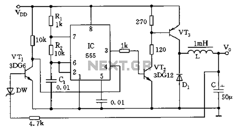
The circuit consists of a 555 timer configured as an astable multivibrator along with resistors R1 and R2 and capacitor C1. It generates an oscillation frequency of approximately 10 kHz with a duty cycle close to 50%. Transistors VT2...
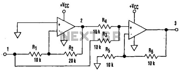
It is well understood that utilizing single-supply operational amplifiers (op amps) can present challenges when implementing simple functions in a bipolar signal environment. Often, this necessitates the use of additional op amps and other electronic components. Considering this, it...
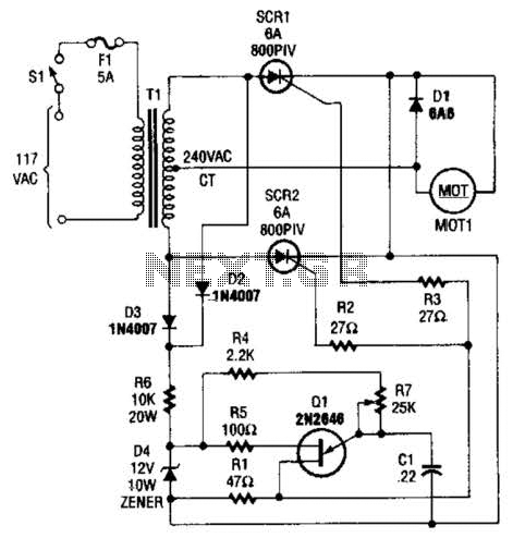
The speed-control switch provides effective control and stability across its entire operating range. This circuit utilizes two SCR devices arranged in a full-wave configuration to manage the DC power supplied to a motor. A center-tapped transformer is employed to...
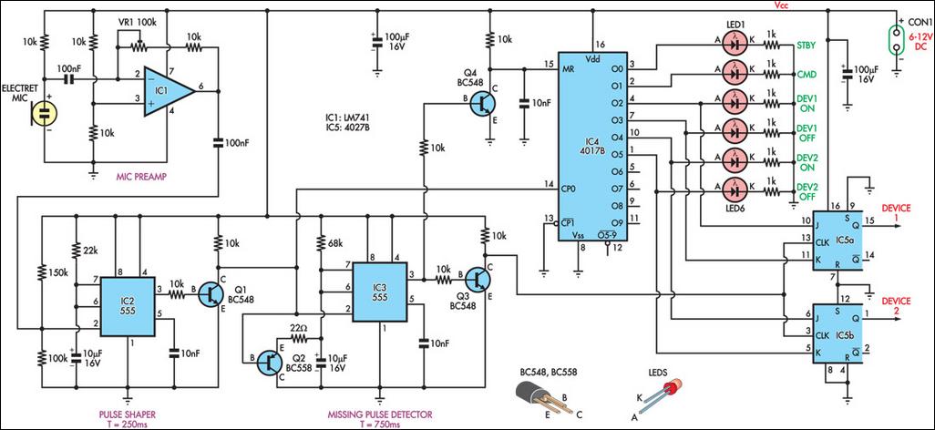
This circuit can switch two or more devices on and off in response to a series of rapid handclaps. The claps are detected by an electret microphone and amplified by a 741 operational amplifier (IC1). IC1 is configured as...
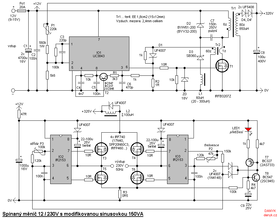
The inverter is designed for powering mains appliances using battery sources. It functions as a switching converter, eliminating the need for bulky, heavy, and costly iron transformers. This design provides advantages such as compact size, lightweight construction, precise output...