
Schmitt trigger
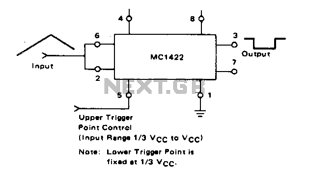
The described circuit employs a Schmitt trigger configuration that utilizes hysteresis to provide stable switching characteristics. The lower trigger point, fixed at a percentage of the supply voltage (Vcc), ensures that the output transitions to a low state when the input voltage falls below this threshold. This fixed lower threshold is essential for preventing noise from causing unintended switching.
The upper trigger point is adjustable through Pin 5, which allows for fine-tuning of the transition from low to high output. This adjustability is crucial in applications where precise control over the switching threshold is necessary. The ability to set the upper threshold slightly below Vcc provides flexibility in accommodating various input signal levels while ensuring reliable operation.
The Schmitt trigger's capability to handle input frequencies up to 50 kHz indicates its suitability for high-speed digital applications. This frequency range allows the circuit to effectively process rapid signal changes without distortion or delay, making it ideal for use in pulse-width modulation, signal conditioning, and other digital signal applications.
Overall, the combination of a fixed lower trigger point and an adjustable upper trigger point, along with the high-frequency operation, makes this Schmitt trigger circuit versatile for a wide range of electronic applications. The design ensures robust performance in environments where signal integrity and precise control are paramount.The lower trigger point is fixed at % Vcc, but the upper trigger point is adjustable by means of Pin 5 from Vi Vcc to slightly less than Vcc The Schmitt trigger will operate with input frequencies up to 50 kHz. 🔗 External reference
Related Circuits
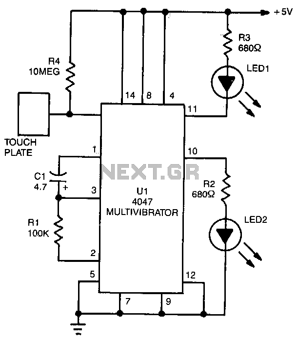
LED1 and LED2 indicators activate and stay illuminated each time the circuit is triggered. During the timing cycle, the Q output at pin 10 of U1 becomes positive when the Q output at pin 11 turns negative. The two...
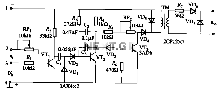
The circuit is designed for inductive loads, specifically within a thyristor power unit, such as a three-phase step-down DC motor speed control and other applications. It is capable of delivering sufficient output power to trigger a thyristor rated at...
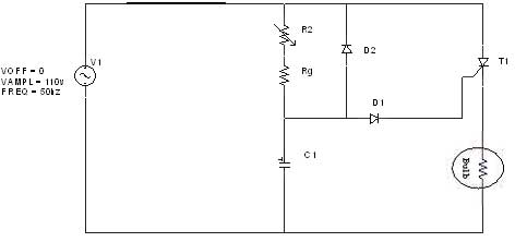
The diagram illustrates an R-C-Diode circuit that provides full half-cycle control (180 electrical degrees). During the positive half-cycle of the SCR anode voltage, the capacitor charges to the trigger point of the SCR, a process governed by the RC...
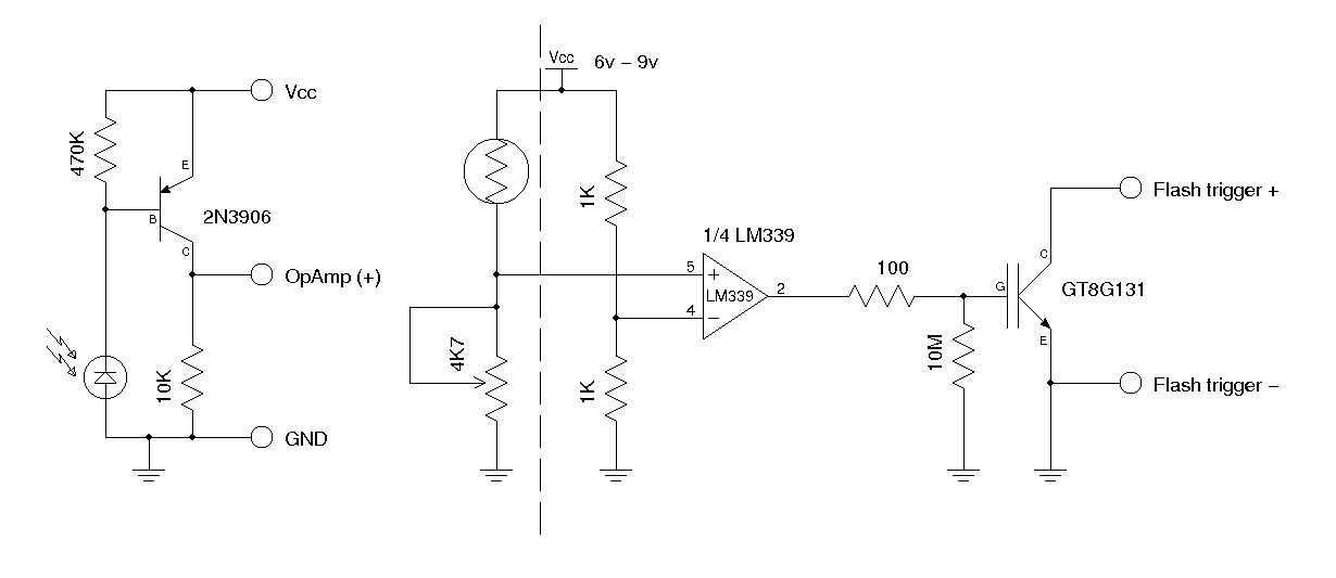
A synchronous camera flash, such as a slave flash, is typically triggered using a silicon-controlled rectifier (SCR). This document presents a circuit designed to trigger a secondary camera flash utilizing an insulated-gate bipolar transistor (IGBT). The use of an...
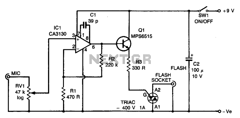
The circuit utilizes an operational amplifier (IC1) configured in a non-inverting amplifier mode. Resistors R1 and R2 establish a gain of approximately 500. The variable resistor RV1 (sensitivity) adjusts the bias of the non-inverting input to the negative supply...
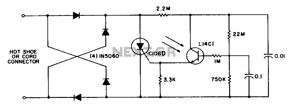
This circuit is utilized for remote photographic flash units that synchronize with the flash attached to the camera. It is designed to connect to the trigger cord or hot shoe of a commercial portable flash unit, allowing the unit...
Warning: include(partials/cookie-banner.php): Failed to open stream: Permission denied in /var/www/html/nextgr/view-circuit.php on line 713
Warning: include(): Failed opening 'partials/cookie-banner.php' for inclusion (include_path='.:/usr/share/php') in /var/www/html/nextgr/view-circuit.php on line 713