Sound trigger for flash unit
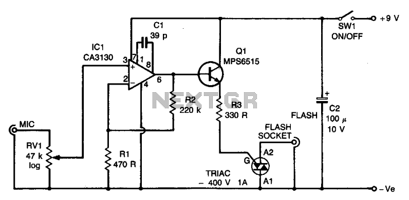
The circuit utilizes an operational amplifier (IC1) configured in a non-inverting amplifier mode. Resistors R1 and R2 establish a gain of approximately 500. The variable resistor RV1 (sensitivity) adjusts the bias of the non-inverting input to the negative supply voltage. Transistor Q1 supplies the necessary high trigger current for the triac. When the microphone detects a sound signal, IC1 amplifies this signal, triggering the triac. This results in a low-resistance path across its A1 and A2 terminals, which are connected through the flash lead to the strobe. The circuit operates with minimal delay, ensuring that the flashgun is activated almost instantaneously upon sound detection.
The circuit design primarily revolves around the operational amplifier IC1, which is critical for amplifying the audio signal captured by the microphone. The configuration of the op-amp in the non-inverting mode allows for a high input impedance, ensuring that the microphone's output is not loaded down, while also providing significant gain due to the resistor network formed by R1 and R2. The gain of 500 indicates that even low-level audio signals can be effectively amplified to a level sufficient to trigger the triac.
The sensitivity of the circuit can be fine-tuned using RV1, which adjusts the voltage at the non-inverting input. This adjustment is crucial for adapting the circuit to different sound levels, allowing it to respond appropriately to varying audio inputs. The biasing of the non-inverting input to the negative supply ensures that the op-amp operates within its linear region, providing consistent amplification without distortion.
Transistor Q1 plays a pivotal role in the circuit by providing the necessary trigger current to the triac. Triacs are semiconductor devices that can control high power loads and are commonly used in applications like flash photography. When the amplified audio signal reaches a certain threshold, Q1 turns on, allowing current to flow through the triac, which then closes the circuit across its A1 and A2 terminals. This action effectively connects the strobe to the power source, enabling it to flash.
The overall design of the circuit is optimized for rapid response, with the operational amplifier and triac working in tandem to ensure that the flashgun is triggered almost instantaneously after the sound is detected. This feature is particularly advantageous in applications such as photography, where timing is critical for capturing fleeting moments. The minimal delay between sound detection and flash activation enhances the circuit's usability in dynamic environments.The circuit is based on operational amplifier IC1 used in the noninverting amplifier mode. Rl and 2 set the gain at about 500. RV1 (sensitivity) biases the noninverting input to the negative supply. Ql provides the relatively high trigger current required by the triac. When a signal is received by the microphone, the signals are amplified (by IC1). The triac is triggered and a low resistance appears across its Al and A2 terminals which are connected via the fiashlead to the strobe. The circuit operates almost instantly, giving very little delay between the commencement of the sound and the flashgun being triggered.
