
Schmitt Trigger Photo switch
The described circuit functions as a Schmitt Trigger, utilizing a cadmium sulfide photo cell as the primary sensor to detect ambient light levels. The circuit is designed to control a relay, which in turn can switch a street lamp on and off based on the light conditions, specifically at dawn and dusk. The relay selected for this application has a coil resistance of 120 ohms and operates at 12 volts, making it suitable for controlling typical street lighting systems.
The photo cell is strategically shielded from direct light emitted by the lamp to avoid erroneous triggering. It is typically mounted above the lamp on a reflector, oriented upward to receive ambient light while minimizing the influence of the lamp's own illumination.
In terms of circuit configuration, the photo cell is connected in series with a potentiometer, allowing for fine-tuning of the voltage at their junction, which is fed to the base of the first PNP transistor (Q1). This arrangement enables adjustment of the circuit's sensitivity to ambient light, effectively setting the threshold at which the relay activates or deactivates.
The two PNP transistors are configured with a common emitter resistor to facilitate positive feedback. This feedback mechanism ensures that when one transistor turns on, the other turns off, thereby creating a hysteresis effect that stabilizes the switching action. Under low-light conditions, the resistance of the photo cell increases, resulting in a higher voltage at the base of Q1 compared to Q2. This causes Q2 to turn on and activate the relay, thus switching the lamp on.
The circuit exhibits specific switching thresholds, approximately 8 volts and 4 volts, determined by the resistor values in the circuit. Adjustments to the resistor, such as replacing the 7.5K resistor with a lower value like 3.3K, can narrow the switching range to approximately 3.5 volts and 5.5 volts, allowing for more precise control over the relay's operation. The potentiometer must be recalibrated to maintain the desired voltage level at the ambient light threshold, typically around 4.5 volts.
Overall, this Schmitt Trigger circuit provides a reliable solution for automatic street lighting control, utilizing simple electronic components to achieve effective light level detection and relay activation.This is basically a Schmitt Trigger circuit which receives input from a cadmium sulfide photo cell and controls a relay that can be used to switch off and on a street lamp at dawn and dusk. I have built the circuit with a 120 ohm/12 volt relay and monitored performance using a lamp dimmer, but did not connect the relay to an outside light.
The photo cell should be shielded from the lamp to prevent feedback and is usually mounted above the light on top of a reflector and pointed upward at the sky so the lamp light does not strike the photo cell and switch off the lamp. The photo cell is wired in series with a potentiometer so the voltage at the junction (and base of transistor) can be adjusted to about half the supply, at the desired ambient light level. The two PNP transistors are connected with a common emitter resistor for positive feedback so as one transistor turns on, the other will turn off, and visa versa.
Under dark conditions, the photo cell resistance will be higher than the potentiometer producing a voltage at Q1 that is higher than the base voltage at Q2 which causes Q2 to conduct and activate the relay. The switching points are about 8 volts and 4 volts using the resistor values shown but could be brought closer together by using a lower value for the 7.5K resistor.
3.3K would move the levels to about 3.5 and 5.5 for a range of 2 volts instead of 4 so the relay turns on and off closer to the same ambient light level. The potentiometer would need to be readjusted so that the voltage is around 4.5 at the desired ambient condition.
🔗 External reference
Related Circuits
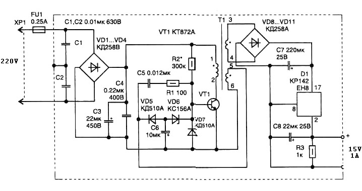
A 15 Watt switching power supply schematic diagram features a pulse transformer T1 constructed on a ferrite core M2500NMS-2 or M2000NM9, with a Sh5h5 size (cross-section of the magnetic coils at the location of 5G—5 mm with a gap...
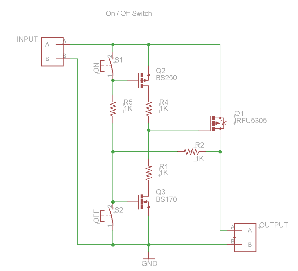
A power button configuration consisting of two buttons, one for turning on and another for turning off. This system is required to switch a voltage of approximately 15 V and a current of up to 10 A for a...
This type of sensor switch is ideal for creating touch-operated bells and buzzers in small toys, which function for a limited duration before automatically shutting off. The trigger's input impedance is very high, allowing the touch sensor switch to...
This project is useful if you wish to experiment with absolute phase, or are just interested in the possibilities of a polarity reversal circuit. In the case of absolute phase, many studies have shown that there can be an...
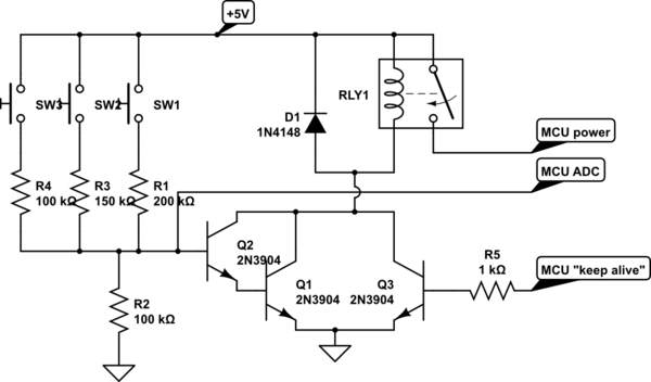
A circuit is being designed that utilizes a combination of switches and resistors to enable a microcontroller to identify which switch has been pressed based on the voltage read, and subsequently perform a switch-specific action. The proposed design incorporates...
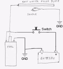
Instructions for constructing a simple Kirlian effect camera to capture high voltage corona discharges around objects, also referred to as aura photography. The Kirlian effect is a phenomenon where high voltage electrical discharges create a visual representation of the energy...