
scr tester

To construct an SCR/TRIAC tester, the following components are necessary: a power supply (9V or 12V DC), a light bulb (as an indicator), a toggle switch, and an SCR or TRIAC to be tested. The circuit should be designed to allow the user to connect the SCR or TRIAC under test to the circuit. The input connections should include the gate, anode, and cathode for SCRs, or the gate and two main terminals for TRIACs. The light bulb serves as a visual indicator of whether the SCR or TRIAC is conducting. When the tester is powered on and the gate is triggered, the light bulb should illuminate if the component is functioning correctly.
The circuit can be assembled on a breadboard or a printed circuit board (PCB) for durability and ease of use. Proper labeling of the connections and the use of color-coded wires will enhance usability. It is crucial to ensure that all connections are secure to prevent false readings. Additionally, incorporating a fuse in the circuit can provide protection against overcurrent conditions.
Overall, constructing an SCR/TRIAC tester is a valuable project for electronics enthusiasts and professionals alike, allowing for efficient testing and troubleshooting of these essential components in various electronic applications.Although you don`t find SCR and Triac in all electronic equipment, this does not mean that both are not important components. You need to learn how to test it so that when you come across one in the future you will know if it is good or bad during troubleshooting.
You can test these components using meters but with the SCR/Triac tester you will fi nd that it is easier to test as compare to using Multimeter. Before I start describing how to build this tester, I guess that it is important to know some of the basic operation of SCR and Triac. SCR stands for silicon-controlled rectifier (or semiconductor-controlled rectifier). It is a four-layer solid state device having an input control terminal (gate-G), an output terminal (anode-A) and a terminal common to both input and output (cathode-C or Kathode-A).
It generally operates as an AC switch for lighting and heating control. In the normal "off" state, the SCR restricts current to the leakage current. When the gate-to-cathode voltage exceeds a certain threshold, the device will turns "on" and conducts current. The device will remain in the "on" state even after gate current is removed so long as current through the device remains above the holding current.
Once the current falls below the holding current for an appropriate period of time, the device will switch "off". The SCR can be found in switch mode power supplies (SMPS). For your information not all SMPS use SCR. The TRIAC is a three-terminal device similar in construction and operation to the SCR. The TRIAC controls and conducts current flow during both alternations of an ac cycle, instead of only one.
Both the SCR and the TRIAC have a gate lead. However, in the TRIAC the lead on the same side as the gate is "main terminal 1-MT1, T1 or even A1, " and the lead opposite the gate is "main terminal 2-MT2, T2 or even A2. " It can be triggered by either a positive or a negative voltage being applied to its gate electrode (with respect to T1, otherwise known as MT1 or A1).
Once triggered, the device continues to conduct until the current through it drops below a certain threshold value, the holding current, such as at the end of a half-cycle of alternating current (AC) mains power. A TRIAC is generally used for motor speed control and in light dimmer. If you repair Laser printer you will find a Triac in the power supply area to control the heating element.
The pinout of a Triac is usually T1 (MT1 or A1), T2 (MT2 or A2) and Gate (G). Just connect the test probes as follows: The `K` probe to `T1`, the `A` probe to `T2` and the `G` probe to `GATE`. Turn on the switch and then press the Gate button on the tester and you should expect the lamp to light.
Conclusion- By having this tester you will not have doubt if the SCR or the Triac will breakdown when under load as compare to using multimeter to test it. By looking at the light bulb you can judge if the component is working or not. If there is a constant light you can be sure it is working. If the light have intermittent flashes and do not light at all then you can suspect that the component under test may have problem.
I suggest that you compare with a known good working component for best result. If using 9 volt does not provide a good result to you then try use 12 vdc to retest and see the result. By the way, you have the choice on how you place the circuit board or components, this entirely depends on your preference and not necessary have to follow the above design.
Take care and may God always bless you and your family. 🔗 External reference
Related Circuits
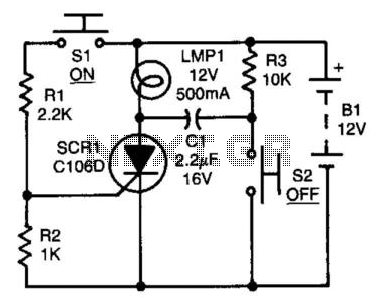
After the SCR is activated, capacitor CI charges up to nearly the full supply voltage through resistor R3 and the anode of the SCR. When switch S2 is later closed, it grounds the positive terminal of CI, causing the...
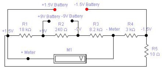
The circuit diagram of a DC battery tester designed by Matthew B. This circuit can measure DC batteries ranging from 1.5V to 9V. Component Parts List: R1 = 18K Ohm, R2 = 240 Ohm, R3 = 8.2K Ohm, R4...
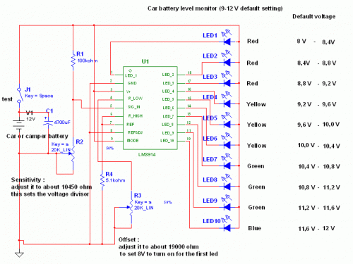
This circuit utilizes the well-known and easily accessible LM3914 integrated circuit (IC). The IC is straightforward to operate, requiring no external voltage regulators due to its built-in voltage regulation capability, and can be powered by a variety of sources....
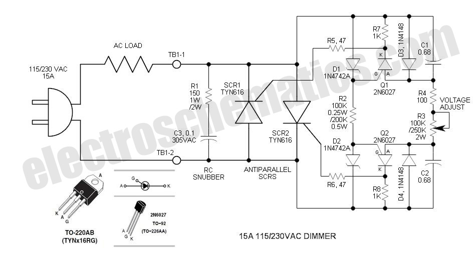
The DIAC is a 28V bidirectional trigger device commonly used in inexpensive phase control applications. Its trigger voltage is relatively high for 115VAC phase control. In the past, a similar low voltage trigger device known as a Shockley diode...
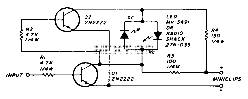
The circuit employs a dual LED configuration. When power is supplied to the probe through the power leads, and the input is connected to a low level or ground, transistor Q1 is turned off. This results in transistor Q2...
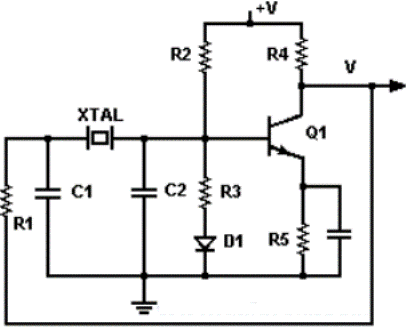
There are various configurations for crystal oscillators, with the most common being discrete and integrated circuits like the Pierce and RLC Bridge. The discrete Pierce oscillator is a suitable choice when good frequency stability and a relatively simple circuit...