
Security Lock with keypad and LCD (PIC16F84A)
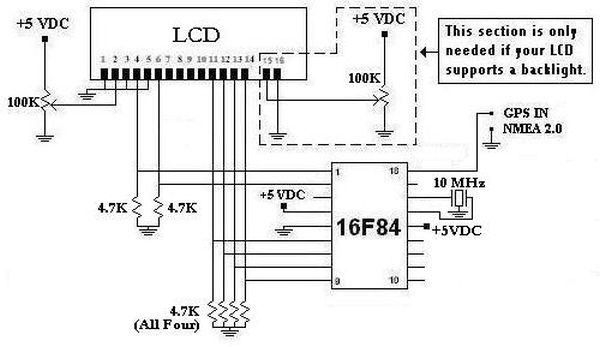
The circuit described utilizes a Microchip PIC16F84 or PIC16F628 microcontroller to interface with an LCD Hitachi display and a 12-key matrix keypad. This configuration allows for efficient control and display of information. The microcontroller, equipped with 16 pins, serves as the central processing unit, managing inputs from the keypad and outputs to the LCD.
The 12-key matrix keypad is connected using only four I/O ports, which optimizes the number of pins used on the microcontroller. The unique method employed for key detection involves measuring the discharge time of capacitors associated with each key, a technique that enhances responsiveness but may be influenced by circuit voltage levels. This requires careful design to ensure stable operation at the specified +5V supply voltage, which is also necessary for the LCD to function correctly.
The system includes a toggle switch that allows the user to select between two operational modes: "Toggle" and "Normal." In the "Toggle" mode, entering the correct password will change the state of the "Enable Signal," allowing for persistent activation of connected devices until the next correct entry. Conversely, in "Normal" mode, the "Enable Signal" remains active for a fixed duration of four seconds after the correct password is entered, providing a brief window for device activation.
This design can be adapted for various applications, including security systems where access control is essential. For instance, it can enable or disable devices such as alarms or electronic locks, ensuring that only authorized users can operate them. The system can also be repurposed for household management, such as controlling TV access for children until certain tasks are completed.
Overall, this microcontroller-based design showcases versatility and efficiency, allowing for the integration of a keypad and LCD display in a compact format while providing essential security features.Finally I was able to control an LCD Hitachi display and a 12-key matrix keypad with only one 16F84 or 16F628. In a near future, I will be able to control a full QUERTY-type keyboard and a LCD display. The biggest improvement on this projects was the compatibility with the Microchip PIC 16F84 and the 16F628, also the 16x1 or the 8x1 LCD Hitachi can be used.
To reduce the cost of this proyect, is possible to remove the LCD and the circuit will work with the beep codes. Basically, the hardware is a mini-terminal controlled by a 16-pin PIC.
As you can see, the 3x4 keypad uses only 4 I/O ports. To determine what key is pressed, I read the discharge time of each capacitor. This is a new technique that I developed since two years ago but finally I was able to test it successfully. The only inconvenience of this method is the reading from the keypad is affected by the voltage of the circuit.
Anyway, the circuit needs exactly +5V because the LCD. The switch labeled as "Toggle" and "Normal" defines the function of the security keypad. With the "Toggle" setting, the "Enable Signal" will toggle each time the correct password is entered.
With the "Normal" setting, each time when the correct password is typed, the "Enable signal" will be ON for only four seconds. Activate an electric or electronic device enable by the signal. Example: A car or any electric machine cannot be turned on until the correct password is provided. To enable or disable a central alarm. Keep a circuit ON or OFF that requieres authorization. (Maybe to keep children without TV until the homework is donde). Security vault - Input the code and an electromagnet will be enable during 4 seconds allowing to open the door.
Security entry port - Only authorized employees can input the code enabling the electromagnetic door lock for 4 seconds. Enable a circuit with one pulse to toggle it.
Related Circuits
This project was initiated in late 2003 with the aim of learning PIC programming. The goal was to create a functional device that performed a specific task. The project involves the design and implementation of a microcontroller-based system utilizing a...
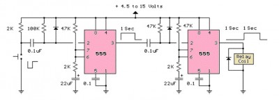
The LM555 timer circuit is similar to the previous design but incorporates two stages, allowing for control over both the pulse width and the delay. The LM555 timer is a versatile integrated circuit widely used in various timer, delay, pulse...
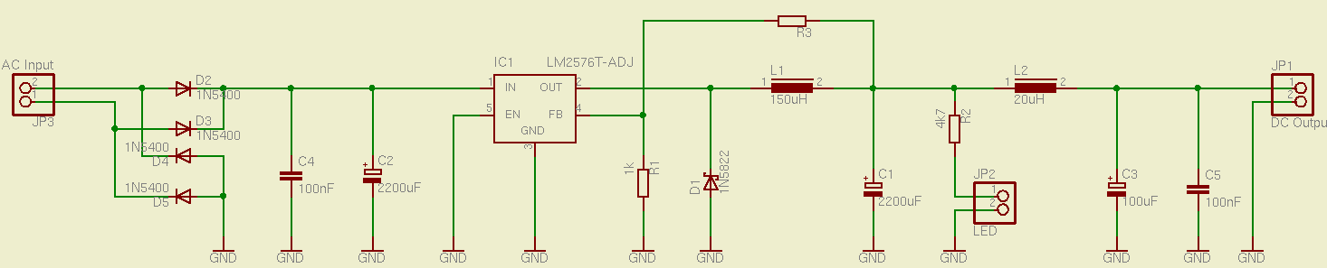
This is a simple and effective switched mode power supply (SMPS) designed to power an LCD monitor. It requires 20V at 2.3A, but the power supply unit (PSU) output voltage can be adjusted in the range of 1.2V to...
This circuit converts the ripple from a wall wart supply to a clean Line x 2 digital clock. Doing it this way eliminates the need to put AC into the unit, which then has to be rectified and filtered...
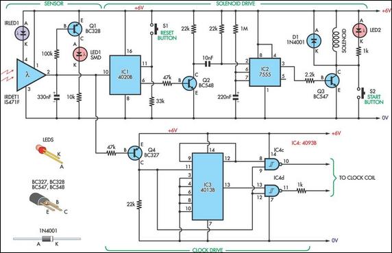
This design allows for the construction of an electromagnetically impulsed pendulum clock with a 1-second beat. The prototype features a pendulum rod measuring 115 cm in length, with a bob adjusted to achieve a 1-second beat. The pendulum is...
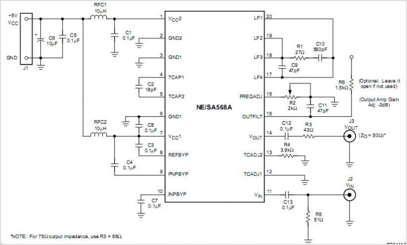
NJM2268 is a dual video 6dB amplifier designed for S-VHS VCRs, high-bandwidth VCRs, and similar applications. One channel features a clamp function that stabilizes the DC level of the video signal, while the other channel operates as a bias...
Warning: include(partials/cookie-banner.php): Failed to open stream: Permission denied in /var/www/html/nextgr/view-circuit.php on line 713
Warning: include(): Failed opening 'partials/cookie-banner.php' for inclusion (include_path='.:/usr/share/php') in /var/www/html/nextgr/view-circuit.php on line 713