
5 Zone Alarm Circuit
The described circuit operates as a security alarm system featuring multiple zones, each utilizing normally closed contacts. These contacts can be implemented using micro switches or standard alarm contacts, typically reed switches, which are known for their reliability in security applications. The system is designed with five zones: Zone 1 serves as a timed entry and exit point, necessitating a delay to allow authorized individuals to enter or exit without triggering the alarm. In contrast, Zones 2 through 5 are configured as immediate zones, designed to trigger the alarm instantaneously upon activation.
For the purpose of ensuring reliable operation over extended wiring distances, the circuit incorporates input capacitors (C1-C5) that provide RF immunity. This feature is critical in environments where electromagnetic interference might affect the performance of the alarm system. Additionally, components C7 and R14 are included to form a transient suppressor, which protects the circuit from voltage spikes that could occur due to switching transients or other electrical disturbances.
A key switch is integrated into the design to facilitate user interaction with the system, allowing for setting, unsetting, and resetting of the alarm. This switch plays a crucial role in the overall functionality, enabling users to manage the security state of the system effectively. The combination of these elements creates a robust alarm system capable of providing security across multiple zones while maintaining reliability and user-friendly operation.Each zone uses a normally closed contact. These can be micro switches or standard alarm contacts (usually reed switches). Zone 1 is a timed zone which must be used as the entry and exit point of the building. Zones 2 - 5 are immediate zones, which will trigger the alarm with no delay. Some RF immunity is provided for long wiring runs by the input capacitors, C1-C5. C7 and R14 also form a transient suppresser. The key switch acts as the Set/Unset and Reset switch. 🔗 External reference
Related Circuits
The application that we propose is a simple filter that limits the acoustic region (20-20000Hz) to the region 20-100Hz. With the manufacture proposed, an active filter can be created to drive a loudspeaker for very low frequencies. This allows...
The post discusses a simple delay ON circuit that enables a connected load to be powered on with a predetermined delay after the power switch is activated. This circuit is applicable for any scenario that requires an initial delay...
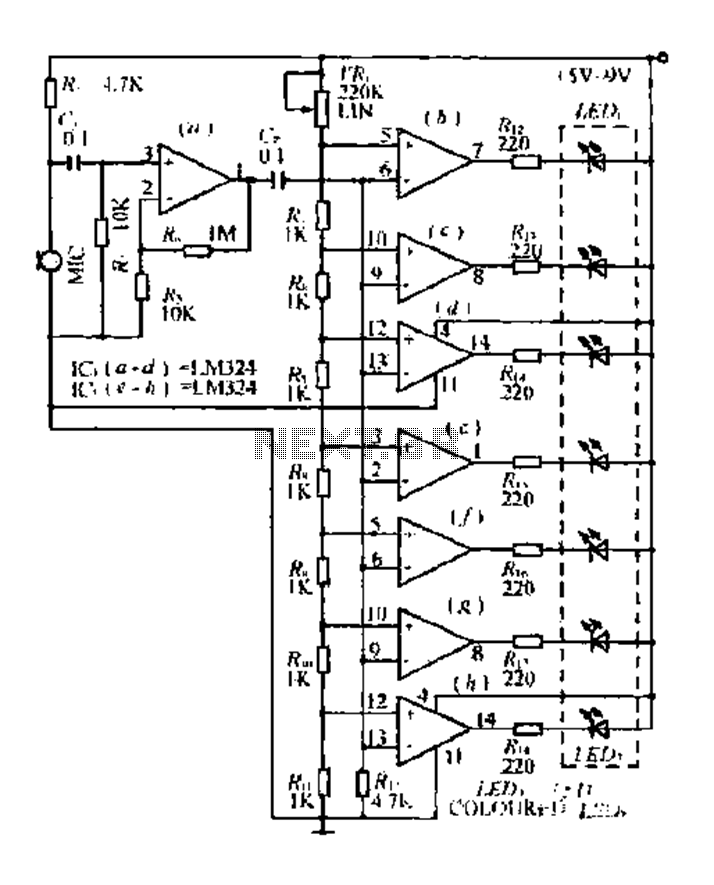
The condenser microphone pickup signal is processed by an integrated circuit (IC) where it is amplified and compared using a comparator circuit. The outputs from the comparators, designated as IC1, IC2, and IC3, provide voltage comparisons based on different...
This design is for an interpolating scanner, a circuit featuring multiple signal inputs, a control voltage input, and a signal output. The output selectively transitions between inputs, smoothly fading from one to the next as the control voltage increases....
This is a 300 W RF amplifier designed for FM transmission, capable of operating within the frequency range of 88 to 108 MHz. The amplifier utilizes two TP9383 transistors, enabling it to deliver up to 300 W of output...
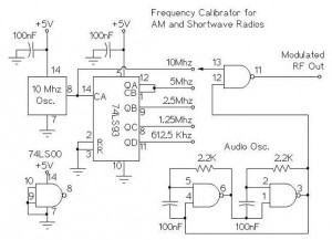
The following circuit illustrates an AM/Shortwave Radio Frequency Calibrator Circuit Diagram. This circuit is based on the 74LS93 IC. Features: The .. The AM/Shortwave Radio Frequency Calibrator Circuit utilizes the 74LS93 integrated circuit, which is a 4-bit binary counter. This...