
Simple phase detector
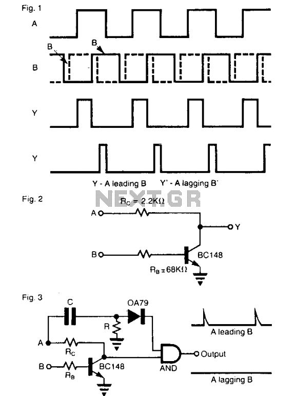
The circuit functions as a phase detector, utilizing an enabled inverter configuration to ascertain the relationship between two input signals, A and B1. The inverter's output, Y, operates based on the logical state of input A. When A is high (logic 1), the output Y reflects the state of B, effectively enabling the transmission of B's logic level. Conversely, when A is low (logic 0), the output Y is forced to a low state (logic 0), rendering it independent of B's state.
Connecting the signals A and B1 to the inputs of the circuit results in the generation of a pulse train signal at the output. The duration of these pulses is directly related to the phase difference between the two input signals. This relationship allows the circuit to measure phase differences within a range of 0 to 180 degrees accurately. The output pulse train can be analyzed to determine the timing discrepancies between A and B1, facilitating phase measurements critical in various applications, including signal processing and communication systems.
Moreover, the circuit can be enhanced by incorporating an AND gate to further analyze the phase relationship. The leading and lagging positions of the signals can be identified, providing additional context to the phase measurement. By evaluating both the phase difference and the leading/lagging information, a complete understanding of the phase relationship between the two signals can be achieved, extending the measurement capabilities to a full 360-degree range. This comprehensive analysis is essential for applications requiring precise synchronization and timing between multiple signals.The operation of the circuit is like an enabled inverter, that is, the output Y = B provided A is high. If A is low, output is low (independent of the state of B). When the signals A and or B1 are connected to the inputs A and of this gate the output Y is a pulse train signal (shown a Y or Yl) which has a pulse duration equal to the phase difference between the two signals.
The circuit is directly suitable for phase difference measurement from zero to 180°. This performance is similar to the circuits like the Exclusive OR gate used for this purpose. With this method leading and lagging positions of the signals can also be found using an AND gate. Phase difference measured along with the leading and lagging information gives complete information about the phases of the two signals between zero and 360°. 🔗 External reference
Related Circuits
A straightforward smoke detector circuit has been presented through a schematic diagram, which can be easily constructed and installed in an area for essential detection purposes. The circuit utilizes the versatile FIGARO TGS 813 gas sensor as the primary...
There is information not included in this main post. Read through the thread for more information on timer calibration and other useful information by cpfers. PEU pointed out that the TX should be connected to serial port pin 2...
Originally, the tank cost around Php 400 but was later sold for approximately a hundred pesos less. Recognizing a great deal, the decision was made to purchase the toy. Opening the toy proved to be somewhat challenging. The track...
FGDF-3 is a three-phase low-temperature iron plating power commutation control switch and electronic circuit. The KGDF-3 serves as a low-temperature iron plating power supply device, incorporating the characteristics of a single-phase low-temperature iron plating power supply. This design facilitates...
This circuit is not open for discussion. Although working perfectly, it was experimental. I will answer no emails in regards to this circuit. If you are looking for a more serious and reliable bug detector, go to the Countersurveillance...
This circuit is a five-channel equalizer designed for a single line channel. The working principle of this series involves a series of frequency filters with a center frequency of 10 Hz. The five-channel equalizer circuit is structured to manipulate audio...