
Precision Light Alarm With Hysteresis Circuit

The TL081 operational amplifier is a high-performance device characterized by low noise and high slew rate, making it suitable for use in comparator applications. In the described Wheatstone bridge configuration, the TL081 compares the voltage across the bridge, which varies based on the resistance of the CDS (cadmium sulfide) cell. As light intensity increases, the resistance of the CDS cell decreases, leading to a change in the voltage levels within the bridge circuit.
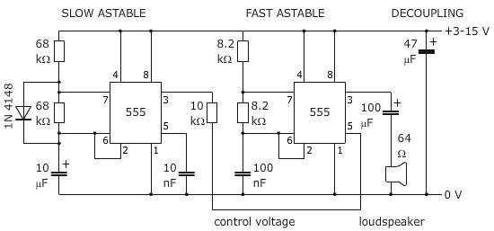
The output from the TL081 comparator is fed into a low-frequency oscillator circuit, comprising components labeled (a) and (b). This oscillator generates a square wave with a frequency of 10 Hz, which serves as a gating signal for the high-frequency oscillators (c) and (d). These oscillators are designed to produce a 1000 Hz signal that can be utilized for further amplification or processing. The alternating activation and deactivation of the 1000 Hz oscillators based on the 10 Hz square wave allows for modulation of the high-frequency signal in response to changes in light intensity detected by the CDS cell.
The inclusion of resistor R3 introduces hysteresis into the comparator circuit, which is a critical feature in preventing rapid toggling of the output state when the input signal is near the threshold level defined by resistor R4. Hysteresis effectively creates a dead zone around the threshold, ensuring that minor fluctuations in the input signal do not cause the output to switch states unnecessarily. This results in improved stability and reliability of the circuit performance, especially in environments where the light intensity may vary rapidly.
In summary, this configuration using the TL081 as a comparator within a Wheatstone bridge circuit is an effective solution for light level detection and modulation, providing a stable output that can be further processed by the subsequent oscillator and amplifier stages. The TL081 is used as a comparator in a Wheatstone bridge circuit. When the CDS cell resistance decreases due to exposure to light, the output from IC2 cause the low-frequency oscillator (a) and (b) to generate a 10-Hz square wave, gating the 1000 Hz oscillator (c) and (d) on and off. This signal drives an amplifier. R3 controls hysteresis, which reduces on-off triggering near the threshold set by R4.
Related Circuits
An alternative to magnetic reed switches for an alarm trip switch is proposed. The circuit requires the switch to be normally closed or held open when the door is shut. A normally closed momentary push button is being considered,...
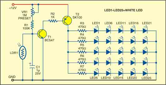
This sunlight-controlled lamp utilizes a light-dependent resistor (LDR) as the sunlight sensor and comprises a total of 25 high-brightness white LEDs. Each row of LEDs is connected in series with separate resistors. The operation of the circuit is straightforward....
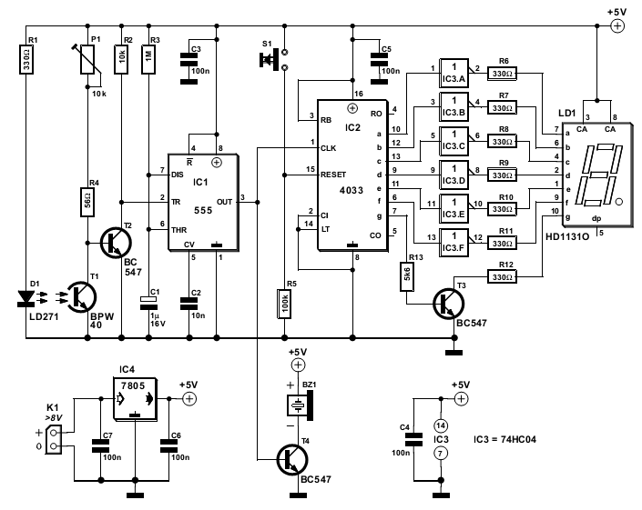
The circuit detailed here counts the number of times an infrared beam is interrupted. It can be utilized to track the number of individuals entering a room or to monitor how frequently an object, such as a ball, passes...
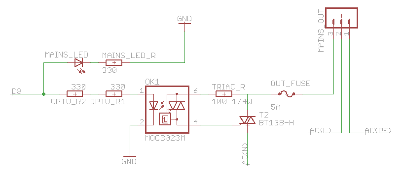
The heatsink on the triac is somewhat unclear. A maximum value of 10°C/W has been calculated, which raises concerns. The calculation is as follows: (maximum temperature - room temperature) / (maximum on-stage voltage * (milliamps / voltage) - junction-to-base...
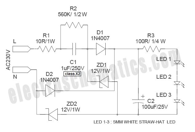
White Light Emitting Diodes (LEDs) now available can serve as a strong alternative to incandescent lamps in lighting applications. Today's White LEDs are... White Light Emitting Diodes (LEDs) represent a significant advancement in lighting technology, offering energy efficiency, longevity, and...
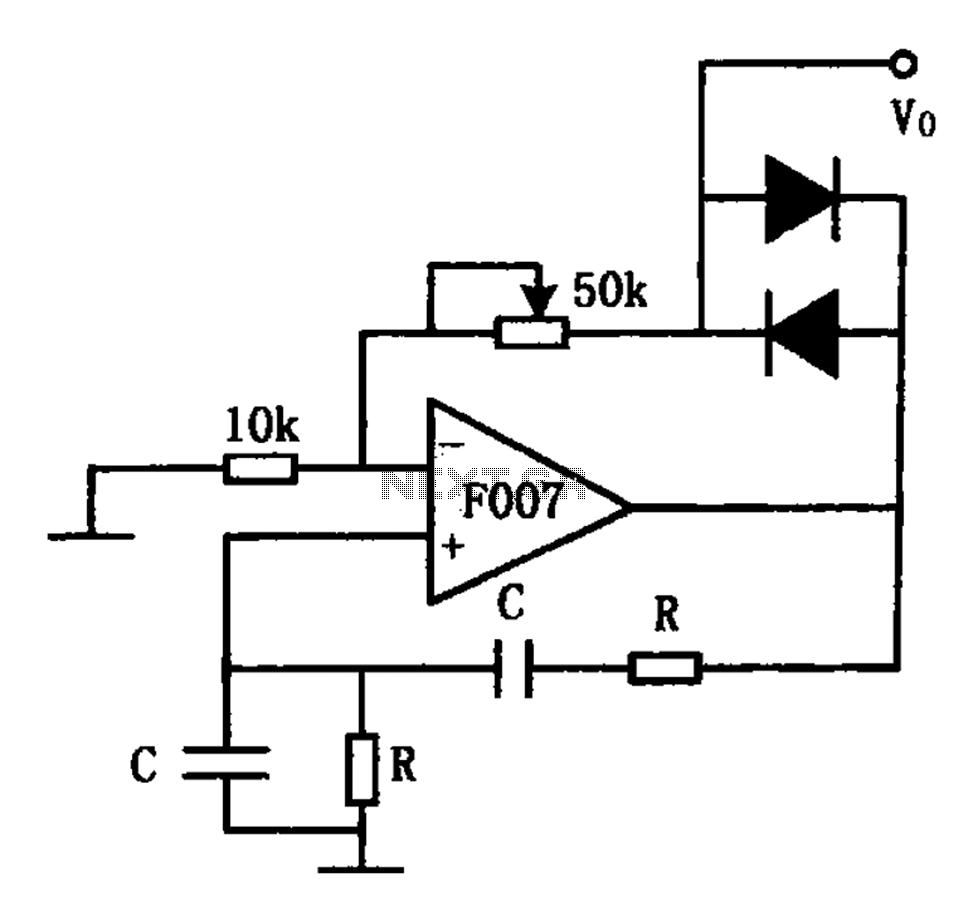
The stable sine wave oscillator circuit is designed to maintain consistent oscillation. The loop gain must be carefully managed; if the gain is excessive, waveform distortion occurs, while insufficient gain can lead to cessation of oscillation. This circuit employs...