
Radio Wave Alarm
The circuit utilizes an integrated circuit (IC1a) as the primary oscillator, generating a carrier frequency just above 1 MHz. This frequency is suitable for medium wave transmission, which typically operates within the 530 kHz to 1700 kHz range. The oscillator is coupled with a sensor, which can be constructed using a simple sheet of tin foil, measuring approximately 20 cm x 20 cm. The sensor acts as a capacitive element, detecting changes in capacitance caused by nearby objects, such as a hand or foot.
The modulation of the carrier signal is achieved through a second integrated circuit (IC1b), which produces an audio frequency tone. This tone serves as a continuous beep that is superimposed onto the carrier wave. The modulation process ensures that the transmitted signal carries the audio frequency information, allowing for detection by an appropriate receiver.
When an object approaches the sensor, the capacitance changes, leading to a drop in the frequency of the carrier wave produced by IC1a. This frequency shift can be detected by a radio receiver tuned just below 1 MHz. The radio will not pick up the steady 1 MHz signal but will respond to the modulation caused by the frequency change, alerting the user to the presence of an intruder.
In summary, this circuit serves as an innovative alert system that utilizes simple components to provide a non-intrusive means of detecting nearby movement. The use of medium wave transmission and frequency modulation allows for effective operation while minimizing the risk of detection by standard radio equipment.This simple circuit is sure to have the police beating a path to your door - however, it has the added advantage of alerting you to their presence even before their footsteps fall on the doormat. The circuit transmits on Medium Wave (this is the small problem with the police). IC1a, together with a sensor (try a 20cm x 20cm sheet of tin foil) oscillates at just over 1MHz. This is modulated by an audio frequency (a continuous beep) produced by IC1b. When a hand or a foot approaches the sensor, the frequency of the transmitter (IC1a) drops appreciably.
Suppose now that the circuit transmits at 1MHz. Suppose also that your radio is tuned to a frequency just below this. The 1MHz transmission will therefore not be heard by the radio. But bring a hand or a foot near to the sensor, and the transmitter`s 🔗 External reference
Related Circuits
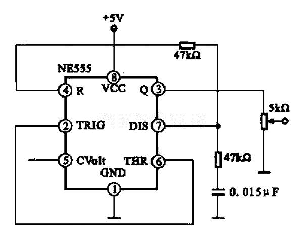
A 1 kHz square wave signal generator is created using a time base circuit with an NE555 timer, combined with a time constant circuit consisting of a 47 kΩ resistor and a 0.15 µF capacitor. The circuit utilizes the...
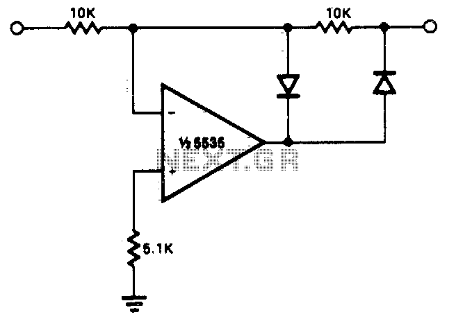
This circuit allows for precise half-wave rectification of the incoming signal. It exhibits a gain of 0 for positive signals and a gain of -1 for negative signals. By reversing the orientation of both diodes, the output polarity can...
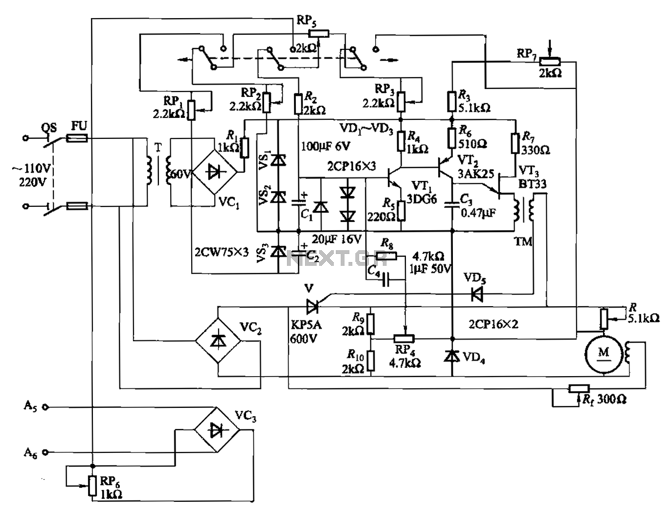
A 100W full-wave single-junction transistor trigger control circuit designed for constant or variable speed control of a wire feed motor. The input control signal consists of a voltage adjusted by the master potentiometer (RPs) and a feedback voltage from...
A noise generator with a wideband output signal is useful for adjusting receivers and various types of HF equipment. A noise generator is an essential tool in the field of electronics, particularly for testing and troubleshooting radio frequency (RF)...

The operating voltage for capacitors C1 and C2 should be raised to 25V if a 12V energy source is used. A general guideline is that the operating voltage of capacitors should be at least double the supplied voltage; for...
C0QBmk~%24(KGrHqIOKkIEq4M%2Bu,)1BK2zHH580Q~~_35.gif)
This time, information will be shared about the schematics of radios, specifically the schematic of a programmer radio, along with the latest information available on Onmilwiki. The schematic of a programmer radio typically includes various components essential for its operation,...