
Half-wave rectifier
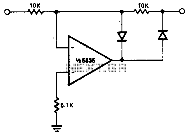
The half-wave rectifier circuit described utilizes two diodes arranged in such a way that they allow current to flow in one direction while blocking it in the opposite direction. The operational amplifier, NE5535, is employed to enhance the performance of the rectifier, ensuring that the output signal is amplified as per the defined gain characteristics. The gain of 0 for positive signals indicates that these signals will not pass through the circuit, while negative signals will be inverted and amplified by a factor of -1, resulting in a mirrored output.
In applications where the output impedance is a concern, additional buffering stages may be implemented. This could involve the use of a voltage follower configuration, which utilizes an operational amplifier to provide a high input impedance and a low output impedance, effectively isolating the rectifier circuit from the load. This buffering ensures that the load does not affect the performance of the rectifier, particularly when dealing with varying input signal characteristics.
The necessity for the output to slew through two diode drops is a critical consideration, as it impacts the response time of the circuit when the input polarity changes. This characteristic is particularly relevant in high-frequency applications, where rapid signal changes are common. The NE5535's capability to operate effectively at frequencies up to 10 kHz with minimal distortion makes it suitable for a range of audio and signal processing applications, where fidelity and accuracy are paramount.
In summary, this half-wave rectification circuit is designed to provide precise signal processing with specific gain characteristics and considerations for output impedance and frequency response, making it a valuable component in various electronic applications.This circuit provides for accurate half wave rectification of the incoming signal. For positive signals, the gain is 0; for negative signals, the gain is — 1. By reversing both diodes, the polarity can be inverted. This circuit provides an accurate output, but the output impedance differs for the two input polarities and buffering may be needed The output must slew through two diode drops when the input polarity reverses. The NE5535 device will work up to 10 kHz with less ttan 5% distortion. 🔗 External reference
Related Circuits
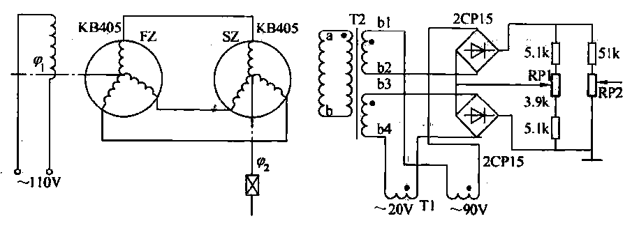
The transmitter (FZ) winding and receiver (SZ) correspond to the three-phase windings connected to a 110V AC voltage supply for transmission. The field winding, early start angle, and receiver output voltage at both ends of the stator windings reflect...
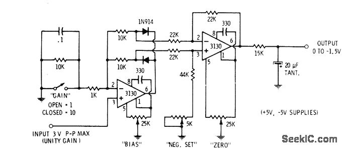
This circuit is utilized in digital voltmeters to convert an AC waveform into a full-wave rectified DC equivalent. The first operational amplifier (op-amp), designated as 3130, functions as a polarity separator. Negative-going signals appear across the upper 10K resistor,...
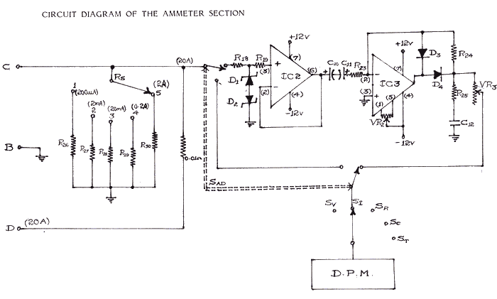
Studying current measurement is essential for various measuring techniques. The current parameter primarily indicates power consumption in a circuit, based on the resistance value. Measuring current is often more convenient than measuring voltage to assess power output and determine...
This circuit is an RMS-calibrated AC voltmeter that provides average readings. Removing capacitor C2 eliminates the averaging function, resulting in a precision full-wave rectifier, while removing capacitor C1 transforms the circuit into an absolute value generator. The operation of...
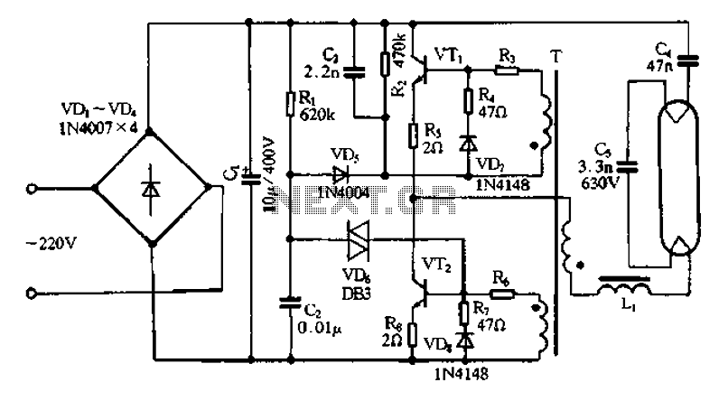
Bridge rectifier circuit in the electronic ballast application circuit The bridge rectifier circuit is a crucial component in electronic ballast applications, primarily utilized for converting alternating current (AC) to direct current (DC). This conversion is essential for powering various electronic...
PWM rectifier power controller power supply. Visit the page to read the explanation about the associated circuit diagram. A PWM (Pulse Width Modulation) rectifier power controller is a sophisticated electronic circuit designed to convert alternating current (AC) to direct current...
Warning: include(partials/cookie-banner.php): Failed to open stream: Permission denied in /var/www/html/nextgr/view-circuit.php on line 713
Warning: include(): Failed opening 'partials/cookie-banner.php' for inclusion (include_path='.:/usr/share/php') in /var/www/html/nextgr/view-circuit.php on line 713