
Isolated Voltage Sensor

The voltage-controlled oscillator (VCO) circuit described is designed for high-voltage measurement applications, specifically within a range of 0 to 600 volts. The circuit employs an optoisolator, which provides electrical isolation between the high-voltage measurement section and the instrumentation, ensuring safety and protecting sensitive components.
At the core of the VCO circuit is capacitor CI, which plays a crucial role in both charging and averaging the input voltage. As the input voltage (V) increases, CI charges until the voltage across it reaches the breakdown voltage of zener diode D1. Once D1 conducts, it activates an avalanche circuit that rapidly discharges CI into the input of optocoupler Q1. This discharge event generates a pulse that corresponds to the input voltage level.
The design also incorporates resistors RI and R2, which limit the current flowing through the circuit and help define the input voltage range. The power dissipation across these resistors is a critical factor that determines the maximum allowable input voltage. The averaging effect provided by CI enhances the circuit's noise immunity, ensuring that transient voltage spikes do not affect the accuracy of the measurement.
The output from the optocoupler is a pulse train whose frequency is directly proportional to the input voltage, allowing for easy interpretation of the voltage level. To achieve linearity in the output signal, a software-based linearization approach is recommended. This involves measuring the pulse frequency output at two distinct input voltage levels, which allows for the establishment of a polynomial relationship between the input voltage and output frequency.
By utilizing the measured periods from these two input levels, a second-order polynomial can be formulated, and the constants k1 and k2 can be determined. This polynomial will provide a linear approximation of the VCO output, making it suitable for various applications that require accurate high-voltage measurements. The zener voltage Vz of diode D1 is also essential in defining the operational characteristics of the circuit, influencing both the charging and discharging cycles of capacitor CI. Overall, this VCO design is a robust solution for high-voltage measurement, combining safety, accuracy, and flexibility through software linearization. A simple voltage-controlled oscillator (VCO), coupled to your instrumentation by an optoisolator, allows you to mea sure high voltages. The component values suit a 0- to 600-V input range (power dissipation in RI and R2 set a limit on the input-voltage range). The circuit"s linearity is not an issue, because you can linearize its output in software. The input voltage (V), charges capacitor CI until zener diode D1 conducts. Then, the zener diode triggers an "avalanche" circuit that discharges CI into optocoupler Ql. After CI discharges, the charging cycle repeats. CI also averages the sensed-voltage level, which thereby provides noise immunity. The optocoupler"s output is a pulse train whose frequency increases with increasing input voltage. To develop a linearizing equation for the circuit, measure its output at two convenient, widely spaced input voltages.
Then plug the resulting periods into this second-order polynomial approximation and solve the two simultaneous equations for the two constants, k1 and k2: Vz is the zener voltage of D1.
Related Circuits
A high voltage power supply is a valuable source that can be effectively used in various applications, such as biasing gas-discharge tubes and radiation detectors. This type of power supply can also serve as a protective measure, such as...
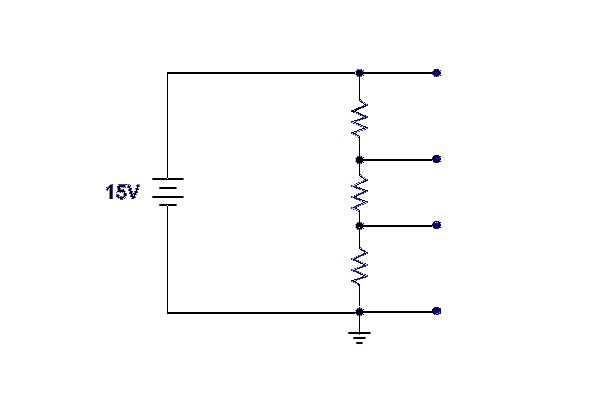
Ground serves as a reference point for the voltage divider, with each successive point above ground indicating the voltage drop across the circuit. For example, with a 15-volt input and 5K ohm resistors, the voltage taps would measure 5,...
The following circuit illustrates a low voltage power supply (PSU) for Nixie tubes utilizing a 555 Timer integrated circuit (IC). The coil used in this schematic is purchased from a store. The described circuit operates as a low voltage power...
This circuit illustrates a color sensor circuit diagram. The design is grounded in the principles of optics and digital electronics. The color sensor circuit typically employs a light-sensitive component, such as a photodiode or phototransistor, to detect and differentiate colors...
This circuit is so sensitive it will detect mains hum. Simply move it across any wall and it will detect where the mains cable is located. It has a gain of about 200 x 200 x 200 = 6,000,000...
The Resistive Sensor Head (A2053) is a Long-Wire Data Acquisition (LWDAQ) device that measures the resistance of up to eleven resistive sensors. These sensors can include 1000-Ω RTDs (Resistance Temperature Devices), 100-Ω RTDs, 120-Ω strain gauges, or similar resistive...