
Sense Fluid Levels With Capacitance

This circuit operates by leveraging the principles of capacitance to monitor fluid levels effectively. The CD4538 monostable multivibrator serves as the core timing element, producing output pulses based on the input trigger conditions. The variable capacitance formed by the copper foil strips acts as a sensor, where the capacitance changes with the fluid level. The closer the strips are to each other, the greater the capacitance, which directly impacts the frequency of the oscillator.
In this configuration, the CD4011 NAND gate chip is utilized to process the signals from the monostable multivibrator. The interaction between the two ICs allows for reliable detection and signal conditioning, ensuring that the circuit can accurately reflect changes in fluid levels. The use of a potentiometer (R3) provides an adjustable threshold for the circuit, allowing for calibration based on the specific application and fluid characteristics.
The design emphasizes the importance of selecting appropriate values for the components involved. The choice of capacitor C3 and resistor R4, along with the variable capacitance sensor, directly influences the responsiveness and sensitivity of the fluid level detection. This circuit can be implemented in various applications, including medical devices, industrial fluid monitoring systems, and automated processes where fluid levels need to be tracked and managed efficiently. Overall, this schematic demonstrates an effective approach to fluid level sensing, merging analog components with practical design considerations.This circuit, which uses a CD4538 retriggerable monostable multivibrator and a CD4011 NAND chip, can sense fluid levels using a variable capacitance ( see the figure ). Such a sensor can be as simple as two adhesive copper foil strips on a saline or blood-supply bag or on another nonmetallic container.
These strips should be as close together and as long as possible, since C ‰ • (A/L). When the fluid level is low (CX = C0), the oscillator`s frequency is high enough so that the trigger input (+TR2) keeps that half of IC2 retriggered, i. e. [overbar Q2] is kept low. As the fluid level rises, so does C, and in turn the frequency goes down. Potentiometer R3 with capacitor C3 sets the level at which the retriggering is no longer continuous. Therefore, what might look like positive pulses at [overbar Q2] are actually "dropouts" from the low state.
As long as the frequency is low enough, these pulses will appear at +TR1, keeping the second half of IC2 retriggered for appropriate values of R4 and C2. Typical values of 50 to 100 pF for CX will produce an oscillator frequency of 10 to 30 kHz, depending on stray capacitance.
🔗 External reference
Related Circuits

A capacitance multiplier simulates a high-capacitance capacitor for analog signal processing. By utilizing a Digital-to-Analog Converter (DAC), it is possible to emulate... A capacitance multiplier is a circuit configuration that effectively increases the apparent capacitance seen at its output compared...
Because it uses few parts, a printed circuit board is not necessary; components can simply be soldered to one another. However, a box is desirable for operating convenience. The case and aerial from a discarded toy walkie-talkie was used...

Consider a capacitor with capacitance C that charges to a voltage V and discharges to 0V at a frequency of 5 times per second. To estimate the average current, also referred to as the RMS current, a rough approximation...

A PC’s serial port provides signal lines that you can use to expand the number of input signals. With some additional circuitry tied to these lines, you can use the port to test digital TTL logic-level circuits. You just...
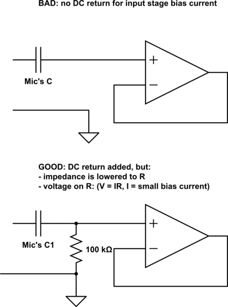
Several KE 4-211-2 Sennheiser microphones were utilized to create a device for acoustic signal analysis. These microphones are connected to a National Instruments data acquisition device via approximately 1 meter long cables, with a sampling rate set at 50...
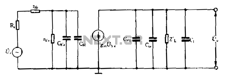
Common emitter amplifier circuit with resistance and capacitance coupling. The common emitter amplifier circuit is a fundamental configuration in analog electronics, widely utilized for its ability to amplify voltage signals. This circuit employs a bipolar junction transistor (BJT) as the...