
TTL signal levels using a serial port MAX232

The described circuit utilizes a PC's serial port to interface with TTL logic-level signals, enabling the testing of digital circuits. The MAX232 integrated circuit serves as a crucial component for converting the RS-232 voltage levels, which typically range from -15V to +15V, into TTL logic levels (0V to +5V). This conversion is essential for ensuring compatibility between the PC and the logic devices being tested.
The 74HC4051 multiplexer is utilized to manage multiple digital input signals. It allows the selection of one of four input signals (A0 to A3) from the device under test through the control of the RTS and DTR lines. The selected signal is routed to the output pin of the multiplexer (pin 3), which is then read by the CTS pin of the serial port. The control logic for selecting the appropriate input is implemented via binary coding, which corresponds to the desired input signal.
The accompanying software, developed in C# .NET, orchestrates the control of the serial port. It sequentially sets the RTS and DTR lines to the required binary combinations, allowing the user to select the desired input signal. The status of the selected signal is then read from the CTS line, providing a straightforward interface for monitoring the digital input.
When constructing the circuit, it is imperative to adhere to the manufacturer's guidelines for the MAX232 and 74HC4051 to ensure reliable operation. This includes proper wiring and the placement of bypass capacitors near the power and ground pins of the ICs to filter out any noise that could affect performance. The option to replace the MAX232 with a MAX225 or MAX233 simplifies the design by eliminating the need for external components, making the circuit more compact and easier to assemble.A PC’s serial port provides signal lines that you can use to expand the number of input signals. With some additional circuitry tied to these lines, you can use the port to test digital TTL logic-level circuits. You just need to convert the TTL logic levels to RS-232 voltages and add a multiplexer to increase the number of signals that the serial port can sense.
The schematic in Figure 1 (shown at the end of this article) uses a MAX232 IC to convert RS-232 voltage levels to TTL-logic levels. A 74HC4051 multiplexer lets you select any of four digital inputs and route them to the serial port. Software available from the online version of this article lets you control the RTS (ready to send) and DTR (data terminal ready) pins in the serial port that select the signal under test.
The CTS (clear to send) pin then reads the signal under test into the PC. The four digital-input signals (A0A3) from your device under test connect to the first four inputs (X0X3) of the multiplexer. Only one of those signals can pass through to the X output (pin 3) at a time. By setting the appropriate binary code on the serial port’s RTS and DTR lines, you can select the signal to pass through the multiplexer.
Table 1 describes the selection of inputs. The PC software, running on Windows XP, sequentially sets those binary combinations on the port’s RTS and DTR lines and reads the digital signal on the CTS line. When you click the Check status” button on the user interface, the software reads and displays the status of the selected bit.
The code is written in Microsoft C# .NET 2008, but it will run on the 2005 version as well. To create the application, launch the project wizard and select the Windows Forms Application” from the C# .NET templates. Place the TextBox, Label, and Button components on the project’s main form and assign titles to them.
You should place the SerialPort component on the design area of the project. Then, set the appropriate parameters for the SerialPort component (port number, baud rate, data bits, and parity and stop bits). When you build the circuit, follow all precautions in the manufacturers’ data sheets concerning the wiring of the MAX232 and 74HC4051.
Remember to place bypass capacitors as close as possible to the IC’s power and ground. You can replace the MAX232 with a MAX225 or MAX233, neither of which requires external components. 🔗 External reference
Related Circuits

This light sensor circuit, utilizing a photosensor, serves as a bridge between light and electronics. It is constructed using an operational amplifier and the PIC16C63 microcontroller to control the sensor. While the circuit is not intended for precision applications,...
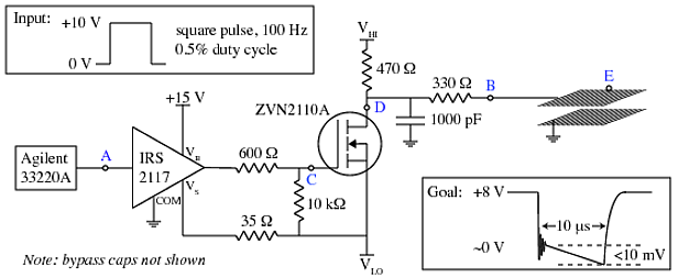
A copper mesh measuring 10 cm x 10 cm is situated in a vacuum chamber and connected to a BNC connector via a 24 cm copper wire. The objective is to rapidly switch the voltage across the mesh (referenced...
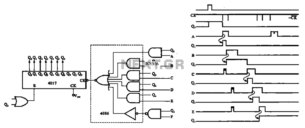
An asynchronous counter is illustrated in this circuit. It operates without a clock synchronization signal, making it suitable for use in a random counter or as an independent unit circuit. An asynchronous counter, also known as a ripple counter, is...
With this circuit can determine whether any of the phones of the same line is busy (it's up the handset), with the help of a LED. The circuit has no measurable effect on the telephone, so that there are...

A 1Hz clock signal generator circuit is presented, which demonstrates a sophisticated clock signal generating mechanism. This circuit can be utilized for digital clocks and timing applications. It comprises a binary counter (CD4060), a JK flip-flop (CD4027), and a...

The circuit illustrated briefly flashes an LED to attract attention and remains illuminated as long as power is supplied. The circuit utilizes the well-known 555 timer integrated circuit (IC) configured as a standard astable multivibrator with resistors RA, RB,...