
Sensitive Continuity Checker
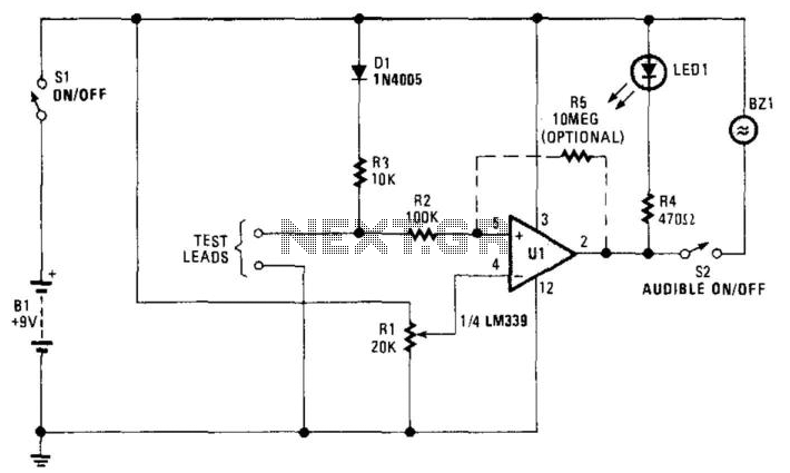
The continuity checker circuit utilizes the LM339 quad comparator, which is known for its reliability and precision in analog signal processing. The circuit configuration includes resistors R1 and R3, which form a voltage divider that sets a reference voltage for the comparator. The unknown resistance, Rx, is connected across the test leads, allowing the circuit to measure continuity by comparing the voltage drop across Rx with the reference voltage.
When the circuit is powered on, U1 compares the voltage from the bridge circuit against the reference voltage established by R1. If the voltage drop across Rx indicates that the resistance is below the set threshold, the output of the comparator goes low, triggering the open-collector output. This action activates the LED indicator, providing a visual signal that continuity exists. Simultaneously, the piezo buzzer B2 is energized, producing an audible alert to signal the user.
The design effectively mitigates the effects of inductive components and low-resistance devices, ensuring that false positives are minimized. The use of an open-collector output allows for flexibility in connecting multiple indicators or alarms if needed.
In summary, this continuity checker circuit is a practical tool for testing electrical connections, leveraging the capabilities of the LM339 comparator to provide reliable continuity indications through both visual and audible signals. The careful selection of components and their arrangement in the circuit ensures accurate performance across a range of applications. This continuity checker (built around an LM339 quad comparator with open-collector outputs) eliminates false r eadings because of coils or low-resistance devices in a circuit. Ul is a comparator that acts as a sensing amplifier for the bridge circuit (Rl and Dl, R3 and the unknown resistance, Rx that is connected across the test leads. When iTis less than this predetermined value (by the setting of Rl), the LED lights and B21 sounds. 🔗 External reference
Related Circuits
Many times we have found itself in the necessity to use a Zener diode and cannot to know the voltage of operation. Many times we cannot read the characteristics or the type that is written on her. In this...
The continuity tester is a useful accessory to an ohmmeter. The unit or component whose continuity is to be checked is connected between terminals E1 and E2. A continuity tester is an essential tool in electronics for verifying the integrity...
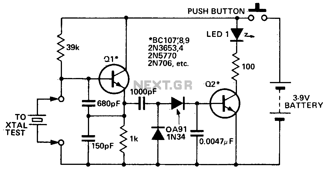
This circuit is designed to check fundamental oscillations. When Q2 conducts, the LED lights up. It operates with A3 HF crystals on a "Go-No-Go" basis. An untuned or 6V, 40mA bulb can be used in place of the Colpitts...
Our CONTINUITY TESTER gives an audible indication of continuity between the probes so you can keep your eyes on the probe tip. Secondly its response-time is very short so that you can make lots of tests very quickly while...
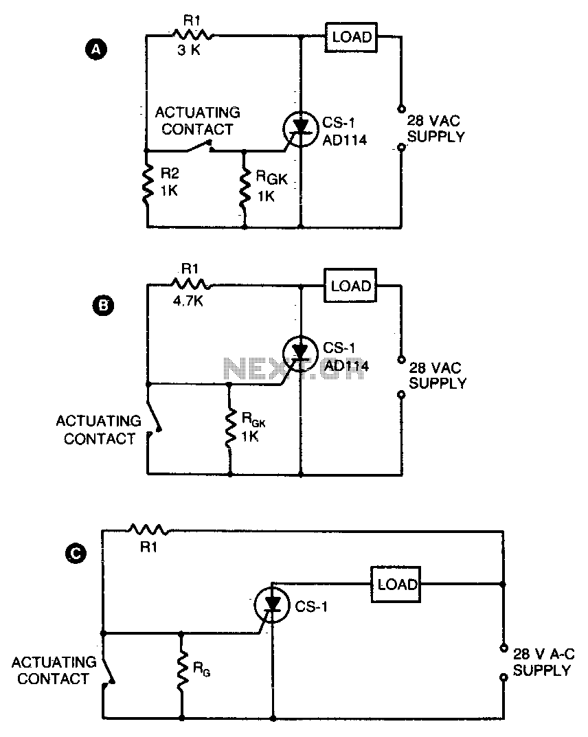
Two simple arrangements for resistive loads are shown in A and B. The circuit in A will provide load power when the actuating contact is closed, and no power when the contact is open. B provides the reverse of...
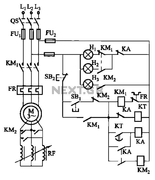
The circuit depicted in Figure 3-165 utilizes a time relay (KT) for controlling the start-up time. Indicator light Hi serves as the power indicator, H2 is designated for the start lights, and H3 functions as the running lights. The circuit...