
Continuity Tester II
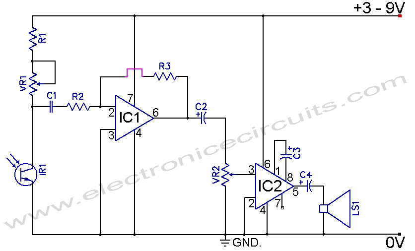
The continuity tester circuit operates by measuring the resistance between two probes. When the resistance is 50 ohms or less, the circuit activates an audio oscillator, which generates a tone through a piezoelectric diaphragm, providing an audible signal to the user. The design incorporates a transistor-based oscillator that is triggered by the detection of low resistance.
The main components of the circuit include the probes, a resistor for setting the threshold resistance, a transistor to amplify the oscillator signal, a piezo diaphragm for sound output, and an LED to indicate power status. The probes are connected to the input terminals of the circuit, allowing for direct measurement of the resistance present between them.
The circuit is designed to ignore resistances above 80 ohms, ensuring that only significant continuity is indicated. This is achieved through careful selection of the resistor values and the transistor characteristics, which are set to provide a threshold response that meets the specified requirements.
The LED indicator is powered simultaneously with the oscillator circuit, providing a visual cue that the tester is active. This feature is particularly useful in environments where audible signals may not be easily heard. The compact design of the circuit allows for easy integration into handheld devices, making it suitable for field testing applications.
Overall, the continuity tester is an essential tool for electronics troubleshooting, providing quick and reliable continuity checks with both audible and visual indicators.Our CONTINUITY TESTER gives an audible indication of continuity between the probes so you can keep your eyes on the probe tip. Secondly its response-time is very short so that you can make lots of tests very quickly while listening for the beep.
And thirdly it only responds to a definite short circuit or one that has a resistance of 50 ohms or less. It will not respond to values above 80 ohms or the voltage drop across a diode. As we mentioned, the circuit detects resistance values of 50 ohms or less between the probes and allows an oscillator to turn ON and produce a tone from the piezo diaphragm. A LED is also included on the board to indicate when the unit is ON as the circu 🔗 External reference
Related Circuits
If you want to test an amplifier, a dummy load may be more convenient for speakers to use than actual speakers, due to noise or damage to the speakers. This circuit behaves in terms of impedance and frequency response...
A multi wire cable tester with a separate LED for each wire. Will show open circuits, short circuits, reversals, earth faults, continuity and all with four IC`s. Designed initially for my intercom, but can be used with alarm wiring,...
The chip tester verifies the functionality and timing of a variety of 7400 series integrated circuits. Students taking Digital Logic Design Lab use these chips often in their laboratory. The IC to be tested should be placed on the...
Infrared Remote Control Tester Circuit. This is a simple circuit that can be built to test infrared remote controls. The circuit utilizes an... This infrared remote control tester circuit is designed to verify the functionality of infrared remote controls commonly...
This simple cable tester can be used to check two-wire cables such as coaxial cables, telephone cables, audio cables, and others. The circuit is powered by a 9V battery. To operate, plug in the cable and press the "TEST"...
This simple circuit is designed to test transistors in a circuit, capable of measuring down to 40 ohms across the collector-base or base-emitter junctions. It is also suitable for checking output power transistors in amplifier circuits. The operation of...