
Multiple Continuity Tester
A continuity tester is an essential tool in electronics for verifying the integrity of electrical connections. It operates by applying a small voltage across the terminals E1 and E2, with the component or circuit segment under test connected in between. If the connection is intact, current flows through the circuit, indicating continuity, often signaled by an audible beep or a visual indicator such as an LED light.
The design of a continuity tester typically includes a power source, often a battery, which provides the necessary voltage for testing. The circuit includes a resistor to limit the current and protect sensitive components. Additionally, an indicator circuit, which may consist of an LED and a current-limiting resistor, is employed to visually confirm the presence of continuity.
In practical applications, the continuity tester can be used to check for open circuits, verify connections in wiring, and troubleshoot faults in electronic devices. It is particularly useful in ensuring that all components in a circuit are properly connected before powering the system. The simplicity and effectiveness of a continuity tester make it a vital instrument for both professional technicians and hobbyists in the field of electronics.The continuity tester is a handy adjunct to an ohmmeter. The unit or component whose continuity is to be checked is connected between terminals E1 and E2.. 🔗 External reference
Related Circuits
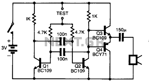
This circuit performs a rapid battery test without requiring an external power supply or costly moving-coil voltmeters. It features two testing ranges: when switch SW1 is configured as indicated in the circuit diagram, the device is capable of testing...
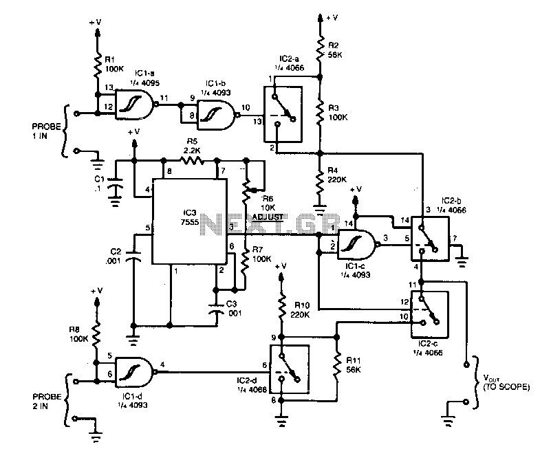
The operation of the unit revolves around three integrated circuits (ICs): a 4093 quad NAND Schmitt trigger, a 4066 quad analog switch, and a 7555 timer. When a high signal is applied to probe 1 input, it is inverted...
The pitch of the tone is dependent upon the resistance under test. The tester will respond to resistance of hundreds of kilohms, yet it is possible to distinguish differences of just a few tens of ohms in low-resistance circuits....
To build a stepper motor tester, the circuit includes two sets of drivers that support both unipolar and bipolar stepper motors. The control circuit and driver circuit are powered by separate supplies, allowing compatibility with a wider range of...
With this tester you can check whether a diode is working properly. In the table you can see what LED to indicate the positions of the switch and condition of the diode. The circuit can be connected to a...
This small circuit is designed to verify the basic functionality of an infrared remote control unit. The circuit utilizes a straightforward approach by connecting a piezo buzzer directly to an IR receiver integrated circuit (IC). This configuration is as...
Warning: include(partials/cookie-banner.php): Failed to open stream: Permission denied in /var/www/html/nextgr/view-circuit.php on line 713
Warning: include(): Failed opening 'partials/cookie-banner.php' for inclusion (include_path='.:/usr/share/php') in /var/www/html/nextgr/view-circuit.php on line 713