
SENSITIVE RF VOLTMETER
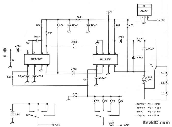
The described circuit comprises several critical components that work together to deliver accurate voltage readings while maintaining meter stability. The peak-reading diode voltmeter operates by first amplifying the input signal through two stages of amplification, which enhances the sensitivity of the measurement. The use of a 100 µF capacitor is crucial as it determines the time constant of the circuit, allowing for a smooth response to voltage changes while avoiding excessive oscillations or overshoot. This is particularly important in applications where transient voltages may be present.
The design incorporates an overdamped meter mechanism, which is essential for preventing the needle from sticking at maximum deflection when there is a sudden change in the input voltage or when the user mistakenly selects an inappropriate measurement range. This feature significantly improves the usability of the voltmeter, especially in field applications where quick adjustments may be necessary.
The inclusion of an SPST toggle switch for additional series resistance allows the user to extend the measurement range of the voltmeter. This X2 function effectively doubles the sensitivity range, providing more flexibility in measuring varying voltage levels without compromising accuracy. The resistance values indicated in the schematic are tailored for a specific configuration that utilizes a 100 µA meter with a 1500 Ω internal resistance, ensuring optimal performance and compatibility.
Overall, this peak-reading diode voltmeter schematic is designed to provide reliable and accurate voltage measurements across a range of conditions, making it a valuable tool in electronic testing and diagnostics.This schematic shows a peak-reading diode voltmeter driven by two stages of amplification. A 100- F capacitor provides a fairly large time constant, which results in satisfactory meter damping. The limited differential output voltage coupled with an overdamped meter prevents most needle pinning when you select an incorrect range position, or make
other errors. An SPST toggle switch selects additional series resistance. This X2 function gives some more overlap of the sensitivity ranges. The resistance values shown are correct for use with a 100- A meter with 1500- © internal resistance. 🔗 External reference
Related Circuits
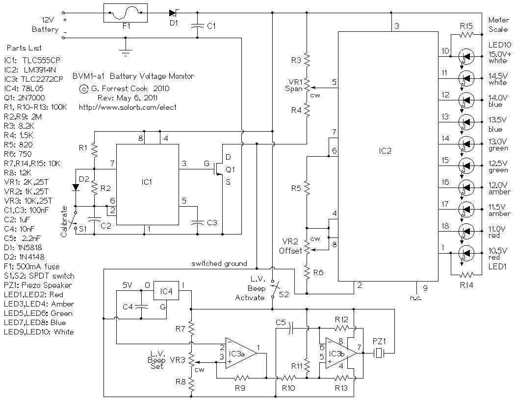
This is a low power voltmeter circuit that can be used with alternative energy systems that run on 12 and 24 volt batteries. The voltmeter is an expanded scale type that indicates small voltage steps over the 10 to...
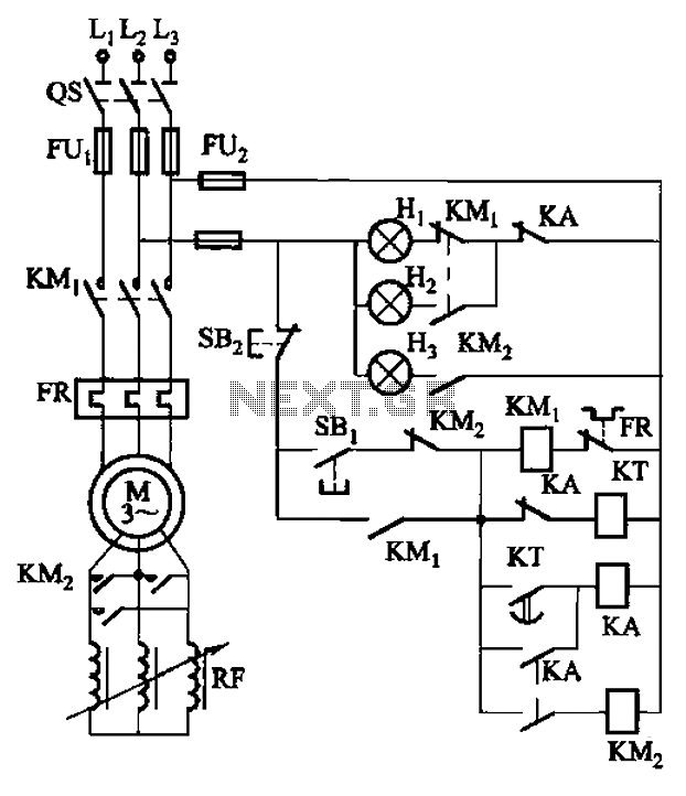
The circuit depicted in Figure 3-165 utilizes a time relay (KT) for controlling the start-up time. Indicator light Hi serves as the power indicator, H2 is designated for the start lights, and H3 functions as the running lights. The circuit...

Using the SLB0586A integrated circuit from Siemens, it is possible to construct a straightforward touch light dimmer circuit that enables the user to adjust the intensity of a lamp. This circuit also incorporates a TIC206D component. The SLB0586A is designed...
This multimeter is designed to measure output voltage and current in a power supply unit (PSU), with the current sense shunt resistor connected in series with the load at the negative voltage rail. It operates using a single supply...
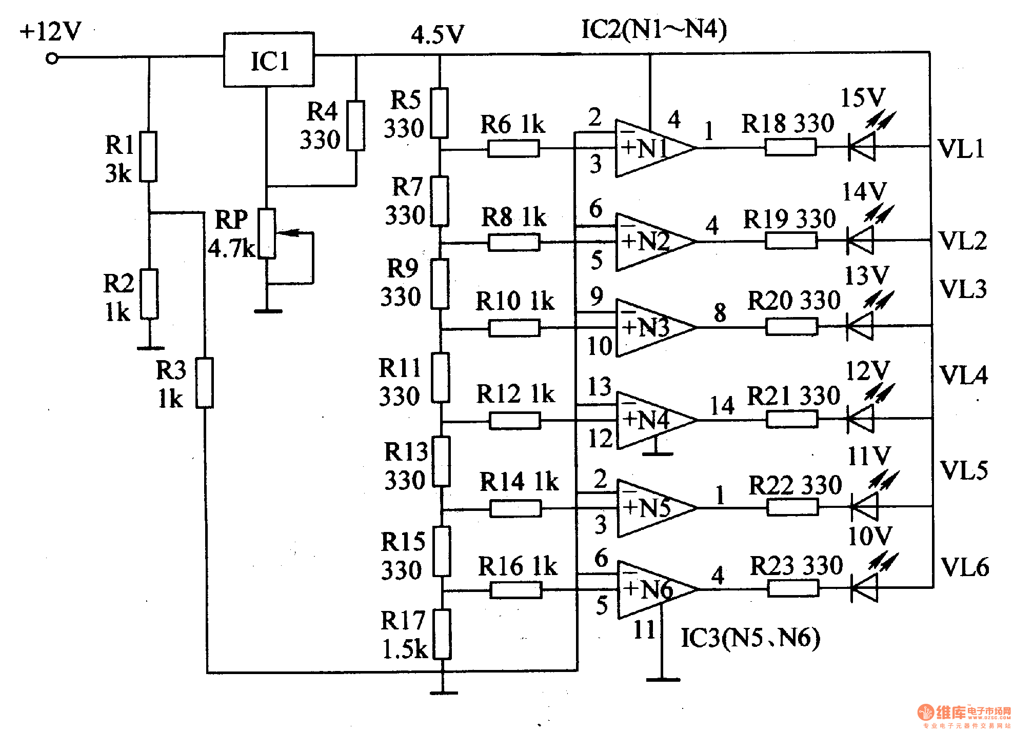
This document introduces an LED car voltmeter constructed using the op-amp LM312 and LED components. It is designed to display six voltage levels ranging from 10V to 15V, with each level representing a 1V increment. The working principle of...

This circuit is designed to provide an affordable method for creating a high impedance voltmeter using a low-cost analog or digital multimeter. The circuit is specifically intended for testing phototransistors. When measuring voltages in high resistance circuits, the resistance...