
Set reset flip-flop circuit

The described circuit is a basic set/reset flip flop configuration utilizing discrete bipolar junction transistors (BJTs). The flip flop consists of two NPN transistors, labeled Q1 and Q2, which are cross-coupled to form a bistable multivibrator.
Upon application of power, one of the transistors will enter the active region, allowing current to flow from the collector to the emitter, while the other transistor remains in the cutoff region. This state is determined by the initial conditions or any small signal present at the bases of the transistors.
To implement the reset functionality, a push button switch is connected to the base of the conducting transistor. When the push button is pressed, it connects the base of the conducting transistor to ground, effectively turning it off. As a result, the collector voltage of this transistor rises, which is coupled to the base of the opposite transistor. This causes the second transistor to turn on, thus changing the state of the flip flop.
The circuit can be powered by a DC voltage source, typically between 5V to 15V, depending on the specifications of the transistors used. Resistors are employed at the bases of the transistors to limit the base current and ensure proper biasing. Capacitors may also be included to improve stability and reduce noise in the circuit.
This discrete flip flop configuration is widely used in digital electronics for applications requiring state retention, such as memory storage, toggle switches, and simple control systems. The simplicity of the design allows for easy troubleshooting and understanding of fundamental digital logic principles.This is an example of a set/reset flip flop using discrete components. When power is applied, only one of the transistors will conduct causing the other to remain off. The conducting transistor can be turned off by grounding it's base through the push button which causes the collector voltage to rise and turn on the opposite transistor. 🔗 External reference
Related Circuits
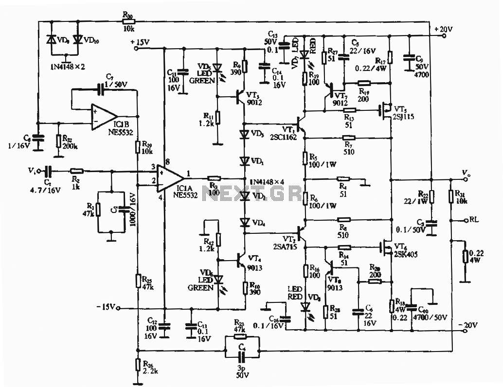
The circuit utilizes an FET amplifier configuration for output, incorporating an NE5532 operational amplifier powered by a 15V supply. The output stage features a FET that amplifies the voltage after passing through several stages. The bias circuit for the...
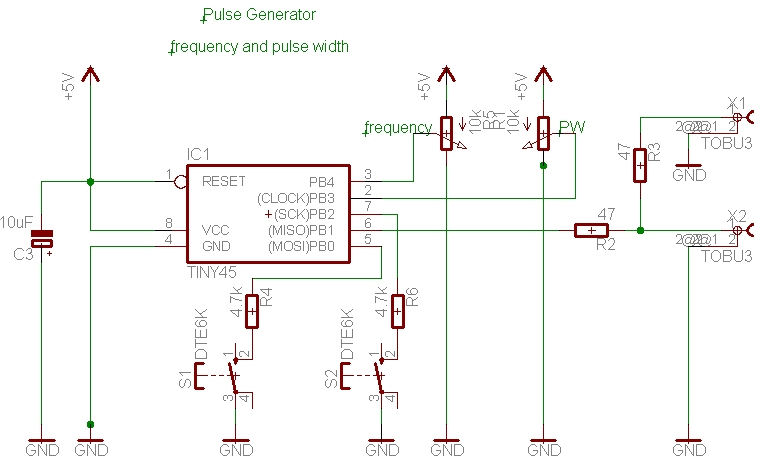
A simple pulse generator with a variable duty cycle and frequency is often useful in the lab to trigger or test other devices, such as a servo with a frequency of 50 Hz and pulses between 1 and 2...
This circuit can be used to operate an electric strike or an electromagnetic lock on a door. It is not the door being opened/closed, but a small electromagnetic strike which unlocks the door. The opener has the following features...
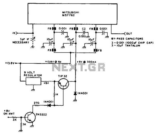
Using a Mitsubishi M57762 amplifier module, this amplifier delivers 20 W output at 1296 MHz. A single 12 V nominal power supply can be used. The Mitsubishi M57762 is a high-performance RF amplifier designed for applications requiring significant power output...

The TDA7262 integrated circuit, manufactured by ST Microelectronics, can be utilized to design a straightforward stereo audio amplifier project. This circuit can deliver a maximum output power of 20 watts per channel. The TDA7262 is a dual Hi-Fi audio...
The electronic dog repellent circuit diagram below is a high-output ultrasonic transmitter primarily intended to act as a dog and cat repeller. The electronic dog repellent circuit utilizes a high-frequency ultrasonic transmitter to emit sound waves that are unpleasant to...