
10hz 60mhz frequency meter

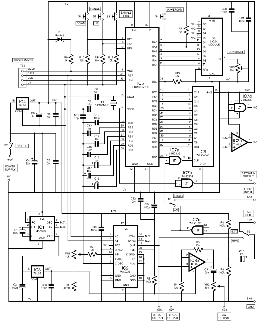
The frequency meter circuit utilizes the PIC 16F628A microcontroller as its core component, which is programmed to perform frequency counting and display the results on a 16x2 LCD screen. The microcontroller interfaces with the LCD through standard parallel communication, allowing for clear and readable output. The 4 MHz crystal oscillator provides a stable clock signal for the microcontroller, ensuring accurate frequency measurements.
The circuit is powered by a regulated 5 V supply, which is achieved through the integration of the 7805 voltage regulator. This regulator ensures that the microcontroller and other circuit components receive a consistent voltage, even if the input voltage varies between 5 VDC and 15 VDC. The design includes bypass capacitors to filter out noise and stabilize the power supply.
To measure frequency, the circuit employs a frequency counting method. The input signal from the device under test is fed into the PIC microcontroller, where it is counted over a predetermined time interval. The result is then calculated and displayed on the LCD. The resolution of 10 Hz allows for precise measurements suitable for various applications in electronics.
Overall, this frequency meter circuit is an effective tool for electronic engineers and hobbyists alike, providing a straightforward solution for frequency measurement across a wide range of applications. Its simplicity in design and implementation makes it accessible for those looking to expand their measurement capabilities in electronic projects.The frequency meter can be used to measure the frequency of 10 Hz-60Mhz. The frequency meter has a level of precision or resolution of 10Hz. The frequency meter can be used to measure the frequency of the oscillator, transmitter, frequency generator, cristal, and others during the working frequency trsebut devices in the range 10 Hz - 60MHz. Circu it frequency meter using PIC 16F628A dibagun and with the viewer of the LCD 16 G— 2. Frequency meter circuit is working with the working frequency of 4MHz crystal. The series is an electronic frequency meter is quite simple to make. The following picture of the frequency meter circuit. The series of frequency meters above basically works with the source voltage 5VDC. In this series of 7805 voltage regulator has been installed, so it can be operated with a voltage of 5 - 15VDC. 🔗 External reference
Related Circuits
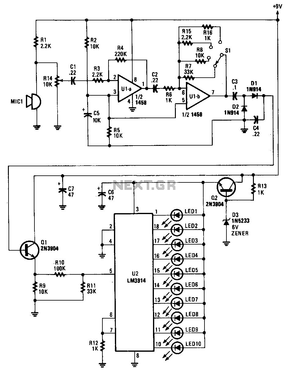
Sounds are captured by MIC1 and sent to the input of the first operational amplifier (op-amp). The signal is subsequently directed to the input of the second op-amp, U1B, where it is amplified by a factor ranging from 1...
Observe the left side of the circuit, which includes a sensing coil and an operational amplifier (op-amp). When connected as shown in the schematic, the circuit did not pick up any signals. A 1mH radial inductor was not available,...
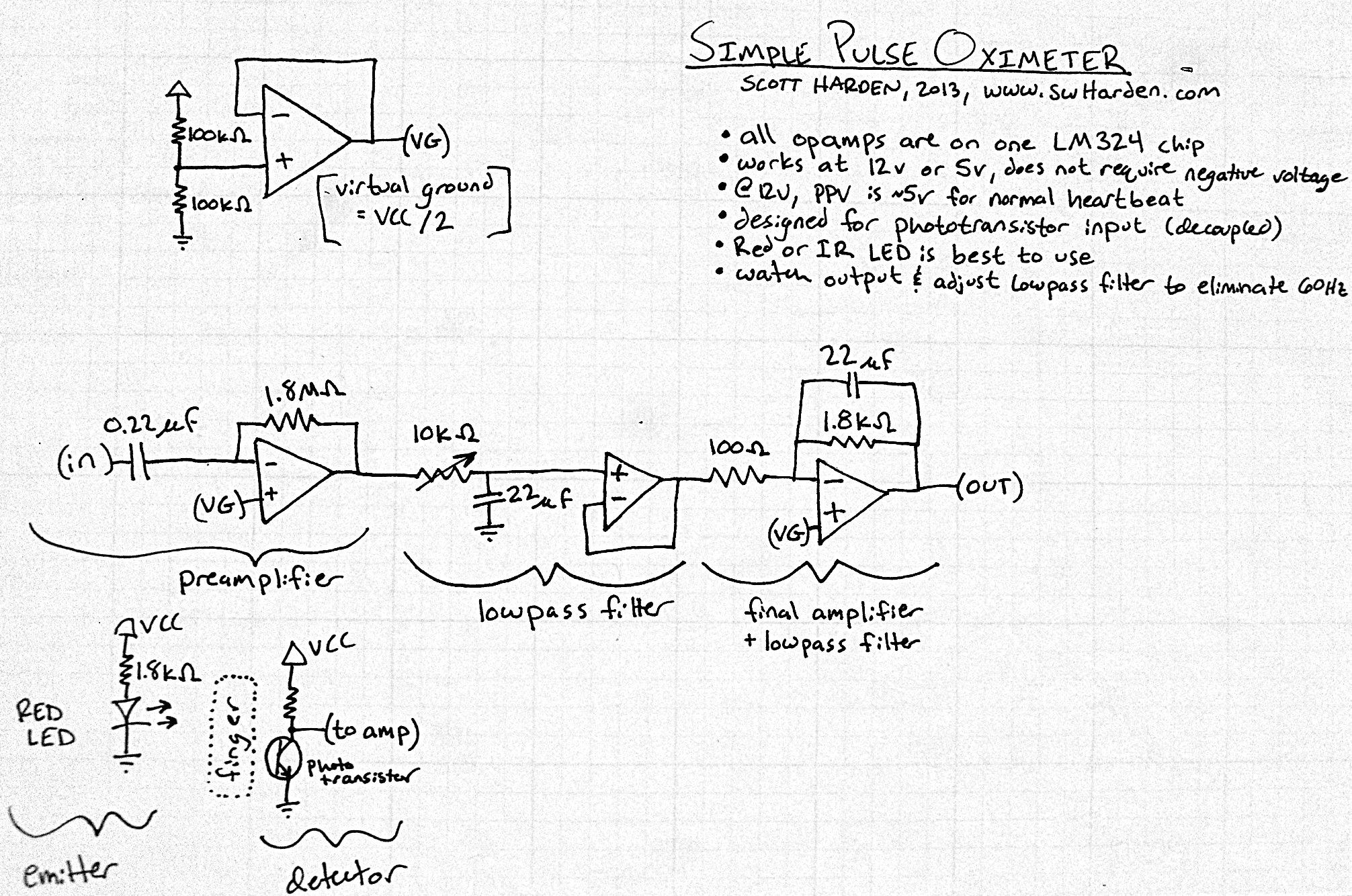
The input capacitor for the phototransistor at the bottom is responsible for feeding the operational amplifier (op-amp). However, the output from the phototransistor consistently remains between ground (GND) and the supply voltage (Vcc). The necessity for an input capacitor...
The functional generator is a device that any well-equipped electronic lab should possess, even if it is not frequently used. However, its convenience is greatly appreciated when needed. This scheme was published in the magazine Everyday Practical Electronics, 2000,...
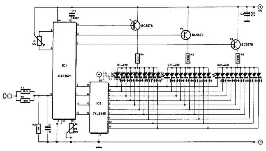
The voltage to be measured is digitized in an analog-to-digital (A/D) converter and then displayed in three decimal digits. The display consists of three groups of 10 LEDs. The meter can only be used for measuring direct voltages. The...
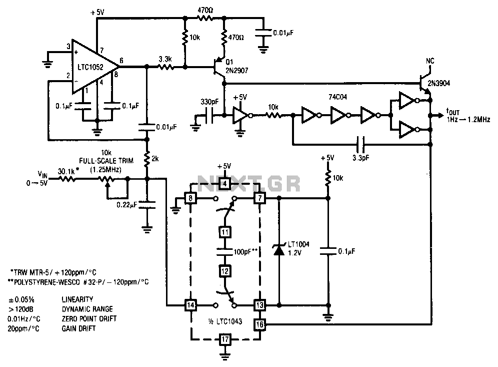
This stabilized voltage-to-frequency converter operates within a range of 1 Hz to 1.25 MHz, featuring a linearity of 0.05% and a typical temperature coefficient of 20 ppm/°C. The circuit is powered by a single 5-V supply. It employs a...