
Short-Range Sonar with the BS2!
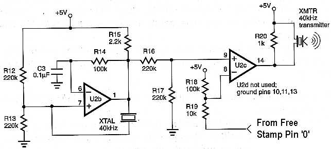
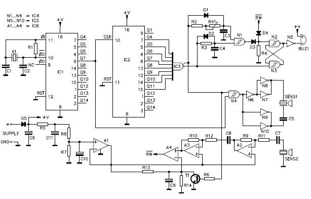
This ultrasonic distance measuring circuit utilizes a pair of ultrasonic transducers operating at a frequency of 40 kHz. The transmitter emits ultrasonic pulses, which travel through the air until they encounter an object. Upon striking the object, the pulses are reflected back to the receiver, which detects the returning sound waves. The time taken for the pulse to travel to the object and back is measured, allowing for the calculation of the distance to the object based on the speed of sound in air.
The circuit design is compact and can be built on a small printed circuit board or a breadboard. The main components include the ultrasonic transmitter and receiver, a microcontroller (such as a Basic Stamp), and associated passive components such as resistors and capacitors, which may be necessary for signal conditioning and processing. The microcontroller is responsible for generating the ultrasonic signal, timing the duration of the pulse, and processing the received signal to determine the distance.
Connections to the microcontroller are essential for proper operation. The "Free Stamp Pin" designation in the schematic indicates where the circuit interfaces with the microcontroller's I/O ports. The user must modify the code to reflect the specific I/O port numbers used in their setup, ensuring that the microcontroller can accurately control the ultrasonic transducer and process the received signals.
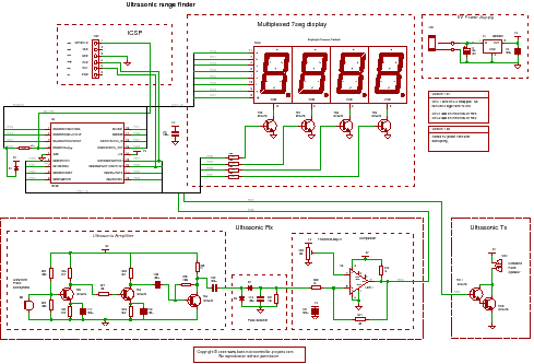
Overall, this circuit is a practical solution for distance measurement in robotic applications, providing a simple yet effective means of obstacle detection and navigation. It is suitable for hobbyists and engineers looking to implement ultrasonic sensing in their projects.This project is best suited for use as a sensor on a robot. This circuit will actually allow you to measure distances from an object. It measures in a `unit` and it`s range is about 10 inches. As the receiver and transmitter, you will use an ultrasonic transmitter and receiver pair tuned to 40khz (see parts list below. ) The circuit is very easy to build, and you can build it on whatever you have laying around. I assembled it onto a Radio Shack pre-etched circuit board - and it only took up about an inch and a half square. Please note that the `Free Stamp Pin` in the schematics refer to the basic stamp i/o port that you connect that part of the circuit to.
You will need to look out for the the three (! FREE STAMP PIN ` ` !)`s in the code, and change the X`s that accompany them to the correct i/o port number. Download the source code by 🔗 External reference
Related Circuits
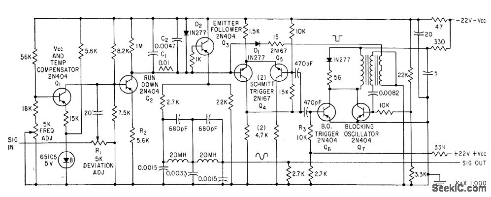
This device is utilized for recording signals from active sonar onto magnetic tape, allowing for subsequent playback to manage land-based sonar systems used in the training of operators. The modulator functions as a sawtooth generator, with its repetition frequency...
In the past, depth measurement of the sea bottom was performed using a "bullet," which was a heavy lead object lowered into the water from a calibrated rope. When the bullet reached the seabed, the depth could be read...
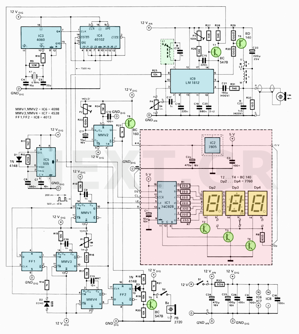
For the PIC sonar range finding project, a PIC microcontroller is ideal. It has a capture timer that can accurately measure the ultrasonic echo time, allowing for the calculation of the distance from the object. The PIC microcontroller serves as...
The receiving systems used with scanning-type echo-ranging equipment are dual-channel systems, which are essential in current video portrayal methods. Deviation indicators, which can be cathode-ray tubes or galvanometers, utilize either a sum-and-difference or a comparison receiving system. These systems...
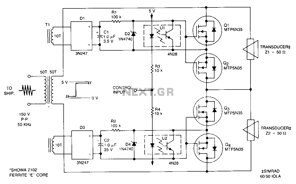
This submersible sonar positioning apparatus primarily comprises dual-opposed ultrasonic transducers that are alternately excited, with the return signals processed and displayed for observation and measurement. Typical transmitter frequencies range from 50 to 200 kHz, and pulse widths can be...
A simple ultrasonic parking sonar electronic project can be designed using this schematic circuit. This ultrasonic parking sonar project features an adjustable detection range from 5 cm to 1.5 meters and a detection angle of 5 degrees. The circuit...