
sonar
The QHB-1 scanning sonar system exemplifies advanced echo-ranging technology, integrating dual-channel receiving mechanisms that enhance target detection and identification. The dual-channel architecture allows simultaneous processing of video and audio signals, crucial for accurate portrayal of underwater environments. The phase measurement technique employed in the system enables precise determination of target location by analyzing the echo signal's phase shift between the two hydrophone-like elements of the transducer.
The keg-shaped transducer design, featuring 48 independent elements, ensures a comprehensive coverage of the surrounding area, facilitating omnidirectional sound radiation during transmission and focused sound reception during echo analysis. The ability to switch between these modes via a keying relay enhances operational flexibility and improves the system's responsiveness to varying underwater conditions.
The video and audio scanning switches operate in tandem, with the video switch providing real-time visual feedback to the operator, while the audio switch enhances situational awareness through auditory signals. The synchronization of the cathode-ray tube's electron beam with the scanning switch is critical for accurate visual representation of target deviations, allowing operators to make informed decisions based on the presented data.
Furthermore, the unicontrol oscillator's design simplifies frequency management, ensuring that both the transmit and receive circuits remain in harmony, which is vital for maintaining signal integrity. The tunable nature of the oscillator allows for adaptability across different operational scenarios, making the QHB-1 system a versatile tool in sonar applications.
Overall, the QHB-1 scanning sonar equipment represents a sophisticated integration of electronic components and signal processing techniques, providing a reliable and efficient means of underwater exploration and target identification.The receiving systems used with the scanning type of echo-ranging equipments are of the dual-channel type, which is required in present methods of video portrayal. Deviation indicators, which are cathode-ray tubes or galvanometers, use either a sum-and-difference or a comparison receiving system.
These systems are used to measure the phase angle o f the echo signal between the two halves of a transducer that has been electrically split so that, on reception, it acts as two independent hydrophones. When the proper circuits are used with these systems the phase angle can be translated into voltage differences, and the video portrayal is indicative of the deviation from the correct target bearing, that isodepression deviation indication (DDI) or bearing deviation indication (BDI).
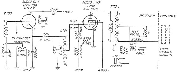
Scanning systems use conventional superheterodyne receivers-one for the video channel and one for the audio channel. The only function of the receiver in the video portrayal is to furnish brightening voltage to the grid of the cathode-ray tube because the scanning and deflection voltages are developed outside the receiver circuits.
The audio channels are used to supply the returning echoes to the operator as an aid in identifying targets. The transducer used with scanning systems is keg-shaped and is mechanically and electrically divided into an even number of independent elements.
In the model QHB-1 there are 48 such elements located so that each element covers an arc of 7 ½ ° of the transducer`s periphery. On transmission, the keying relay connects all the elements in parallel so that sound power is radiated in all directions simultaneously, whereas on reception the elements are connected so as to form a sharp beam in the horizontal plane.
The output of each element is connected through its individual preamplifier to its corresponding element on each of the two scanning switches. The video scanning switch is driven at a constant rate and has a control transformer geared at a 1-to-1 ratio with it.
The output of this transformer controls the positioning of the electron beam of the cathode-ray indicator so that the electron beam synchronizes in azimuth bearing with the scanning switch. The audio scanning switch and the video switch are mechanically and electrically identical, but they differ in application.
The audio switch is positioned by a servo system and must be manually trained to the desired bearing. The receiving system described in the following paragraphs is that of the QHB-1 scanning sonar equipment.
The QHB-1 system was chosen for discussion because its method of video portrayal follows the conventional design and it can be considered a typical system. The block diagram is shown in figure 7-1. The receiver-converter includes separate video-channel and audio-channel receivers for the signals from the corresponding scanning switches.
In this system a tunable oscillator supplies a frequency to the first mixers in both channels and also to the converter, which produces the transmitted frequency. This oscillator identifies the circuit as the unicontrol system because it enables a single control to tune the receivers and the transmitter at the same frequency.
In the receiver-converter a master fixed-frequency 65 kc oscillator (not shown in figure 7-1) modulates a 90. 5 kc signal (arbitrarily selected) from the unicontrol oscillator, and the 25. 5 kc frequency difference is amplified in the transmitter power amplifier. The i-f stages of both receiver channels are tuned to 65 kc. The first mixer in the receiver channels automatically produces an intermediate frequency of 65 kc because the 25.
5 kc received signals are mixed with the 90. 5 kc output of the unicontrol oscillator. The frequency of the unicontrol oscillator may be varied from 87 to 94 kc to produce a variation in transmitted frequency of from 22 to 29 kc. The transducer is operable between 24 and 27 kc, 🔗 External reference
Related Circuits
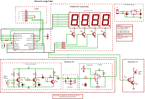
For the PIC sonar range finding project, a PIC microcontroller is ideal. It has a capture timer that can accurately measure the ultrasonic echo time, allowing for the calculation of the distance from the object. The PIC microcontroller serves as...
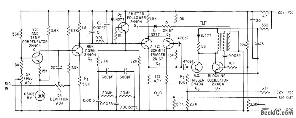
This device is utilized for recording signals from active sonar onto magnetic tape, allowing for subsequent playback to manage land-based sonar systems used in the training of operators. The modulator functions as a sawtooth generator, with its repetition frequency...
This circuit has an automatic switch on for the rear gear, a LED bar graph display, and an audible beep on the last LED. It features a "good old" design style with no microcontrollers. Based on an ultrasonic amplifier...
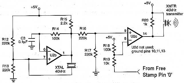
This project is ideal for use as a sensor in a robotic application. The circuit enables distance measurement from an object, with a measurement range of approximately 10 inches. An ultrasonic transmitter and receiver pair, tuned to 40 kHz,...
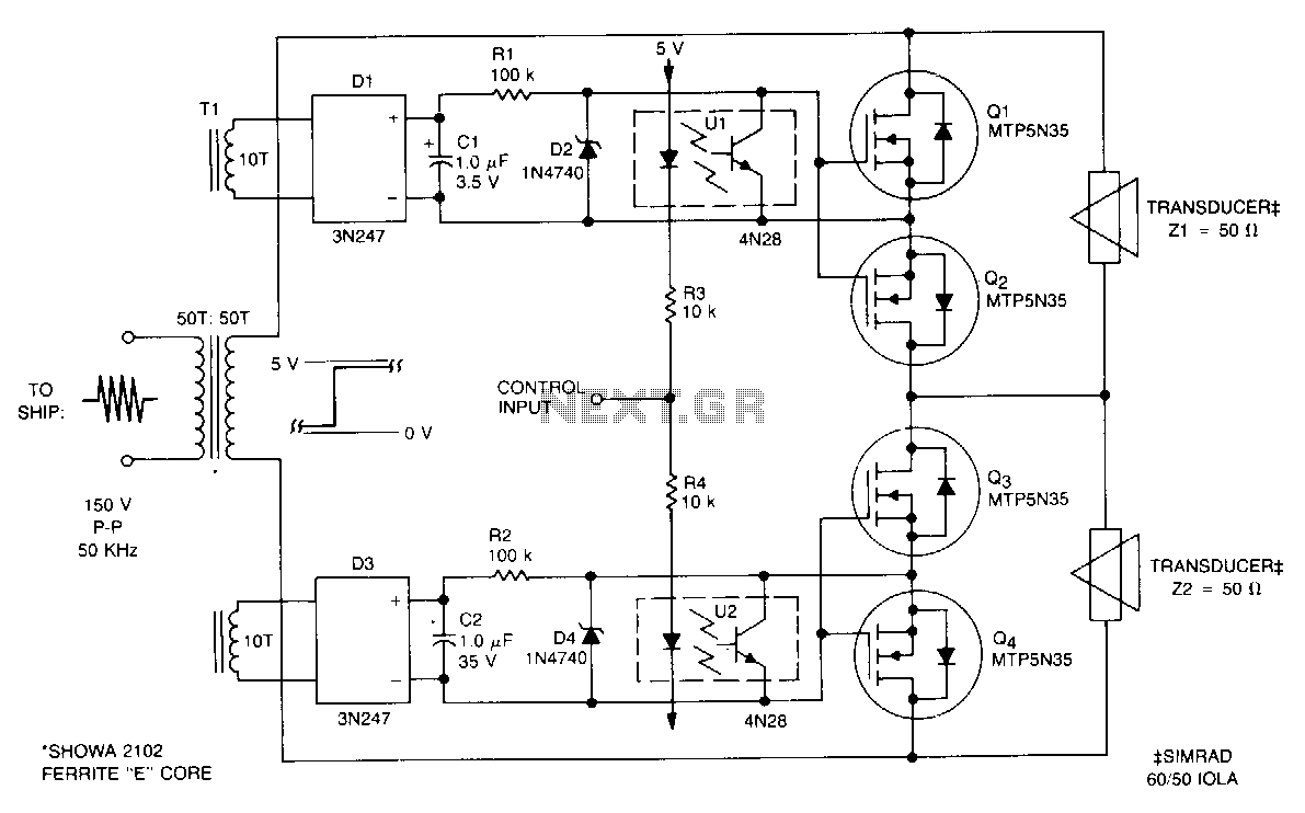
This submersible sonar positioning apparatus primarily comprises dual-opposed ultrasonic transducers that are alternately excited, with the return signals processed and displayed for observation and measurement. Typical transmitter frequencies range from 50 to 200 kHz, and pulse widths can be...
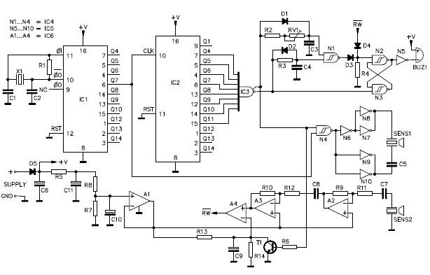
A simple ultrasonic parking sonar electronic project can be designed using this schematic circuit. This ultrasonic parking sonar project features an adjustable detection range from 5 cm to 1.5 meters and a detection angle of 5 degrees. The circuit...