
Shortwave Converter For Am Car Radios
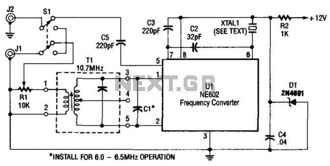
The circuit employs the Signetics NE602, a dual balanced mixer and oscillator, which is adept at handling radio frequency signals. The NE602 operates by mixing the incoming RF signal with a local oscillator signal generated by the circuit, allowing for the desired frequency conversion. The tuning capability is achieved through the use of an AM car radio, which acts as a tunable IF amplifier, effectively amplifying the selected frequency range and providing a clear output.
The output is accessed at J2, which is connected to the auto antenna, facilitating the reception of the modulated signals. The choice of the crystal (XTAL1) is crucial for proper tuning; it must be selected to be approximately 1 MHz below the target frequency. For instance, to tune into frequencies between 9.5 and 9.8 MHz, a crystal with a frequency of 8.5 to 8.8 MHz is necessary. This ensures that the mixer can effectively down-convert the incoming RF signals to a manageable IF frequency that the AM car radio can process.
In summary, this circuit design efficiently leverages the NE602 mixer and an AM car radio to create a versatile frequency converter capable of tuning within a specified range, utilizing appropriate crystal selection for optimal performance. Using a Signetics NE602, this converter tunes the 9.5- to 9.8-MHz range. An AM car radio is used as a tunable IF amplifier. Output is taken from J2, the auto antenna. The crystal (XTAL1) can be a frequency about 1 MHz below the desired tuning range; for 9.5 to 9.8 MHz, an 8.5- to 8.8-MHz crystal should be used. 🔗 External reference
Related Circuits
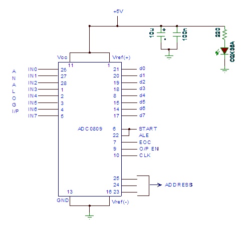
Analog to digital converter modules are utilized in microcontroller-based projects where analog signals need to be transformed into digital signals for further processing in a microcontroller. The integrated chip employed for this purpose is the ADC 0809. This post...
The schematic can be downloaded below. It is important to review it as it will serve as a reference for matching the circuit being constructed. The provided schematic serves as a critical reference for the circuit design process. It outlines...
The result displayed on the LCD is incorrect; the thermometer shows a reading of 414 degrees instead of the actual room temperature. Assistance is needed to determine whether the issue lies within the hex file or the sensor itself....
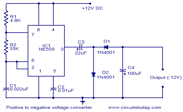
This circuit diagram illustrates the method for obtaining a negative voltage from a positive voltage supply. An additional benefit of this circuit is that the negative voltage, combined with the original positive supply, can be used to simulate a...
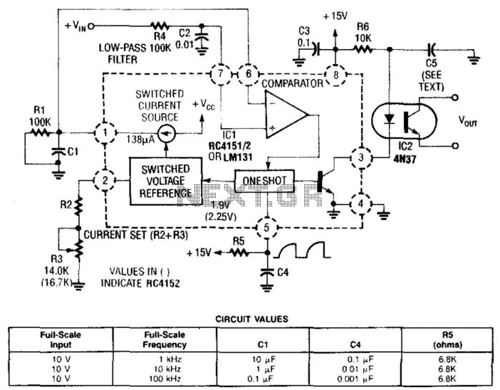
In this circuit, a Raytheon RC4151 or National LM131 is utilized alongside an optocoupler for applications where input-to-output isolation is desirable. Circuit values are indicated in the figure for various applications. The circuit employs a Raytheon RC4151 or National LM131,...
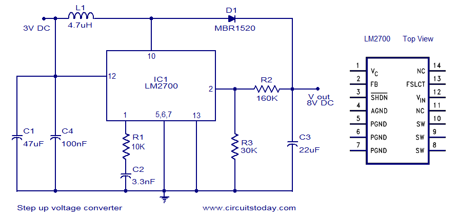
A simple DC to DC step-up voltage converter circuit schematic using the LM2700, which is a step-up switching converter. The LM2700 is a versatile step-up switching converter designed to efficiently convert a lower input voltage to a higher output voltage....