
shortwave radio receiver circuit project
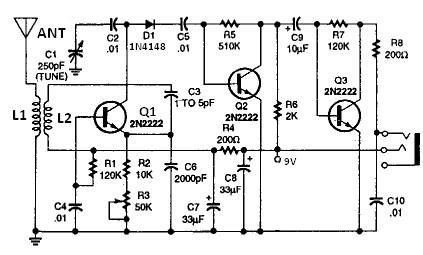
The circuit utilizes a pair of coils, L1 and L2, wound around a PVC pipe to form inductors. The choice of 20-gauge insulated hookup wire ensures adequate current handling and durability. The number of turns in each coil is critical for tuning the circuit to the desired frequency; therefore, the ability to modify the turns or the capacitance value of C2 allows for flexibility in frequency selection.
The amplifier stage, consisting of transistors Q2 and Q3, is designed to provide sufficient gain to drive audio output devices such as headphones or small speakers. This configuration allows for direct amplification of the audio signal detected by diode D1, ensuring that the output signal is strong enough for practical use. The option to replace resistor R3 with a potentiometer introduces a variable resistance that can be adjusted to control the volume level, enhancing user experience.
The inclusion of R4 and C4 as a low-pass filter plays a significant role in maintaining the overall stability of the circuit. This filter effectively attenuates high-frequency noise, which can degrade the audio quality, thus ensuring a cleaner and more enjoyable listening experience.
Furthermore, the voltage regulation aspect of the circuit is managed by diodes D2, D3, and D4. This arrangement provides a stable voltage supply to the amplifier (Q1), which is crucial for consistent performance. By minimizing voltage drift, the circuit achieves reliable operation over varying conditions, which is particularly important in audio applications where fluctuations can lead to distortion or other undesirable effects.
Overall, this circuit design exemplifies a practical approach to audio amplification, incorporating essential features for tuning, stability, and user control, making it suitable for various audio applications.All coils are designed using an inch diameter pvc pipe using 20 gauge insulated hookup wire, L1 require 6 turns and L2 require 14 turns. You can add turns to or subtract turns from L(or change C2) to receive other frequencies. Q2 and Q3 form an amplifier, which has sufficient output level to directly drive headphones or a small speaker, amplify
the detected audio signal output from D1. R3 can replaced with a 2kohms potentiometer, if you want to use it as an volume control. R4 and C4 form a lowpass filter that maintains circuit stability and improves the receiver`s sound quality. D2, D3, and D4 implement a low-cost voltage regulator to keep the voltage supplying Q1fairly constant, which minimizes drift.
🔗 External reference
Related Circuits
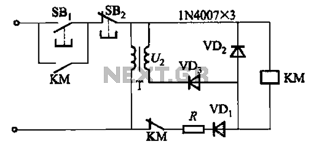
An AC contactor DC transformer circuit operates as a voltage regulator for AC applications. DC contactors come in various types. AC contactors are electromechanical devices used to control the flow of electrical power in AC circuits. They function by opening...
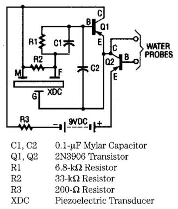
The moisture detector utilizes two transistors and a piezoelectric transducer to emit an alarm tone when water is detected. Transistor Q1 functions as a crystal-controlled oscillator, employing a portion of the piezoelectric transducer XDC, which consists of two piezoelectric...
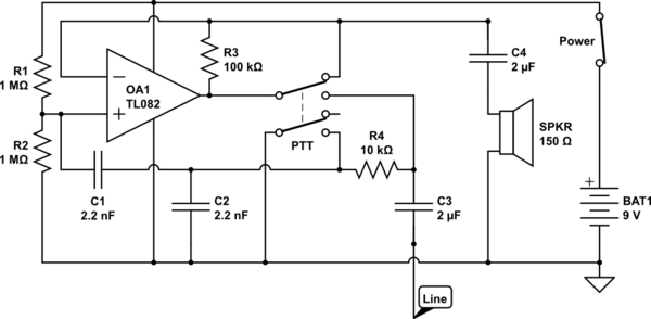
The circuit operates in receive mode, with the Push-To-Talk (PTT) switch enabling transmit mode. The speaker functions as both a microphone and a speaker. Most systems observed utilize a rocking armature transducer for the speaker. There is no base...
The circuit of the unit is fairly simple, but is a bit irksome to set up. The reason is that obtaining matched FETs is not easy, so I had to make sure that the circuit would work with off-the-shelf...
The American Electrician describes a glass battery jar measuring six inches by eight inches, wound with 60 to 80 turns of American wire gauge No. 18 B & S magnet wire. Inside this jar is a primary winding consisting...
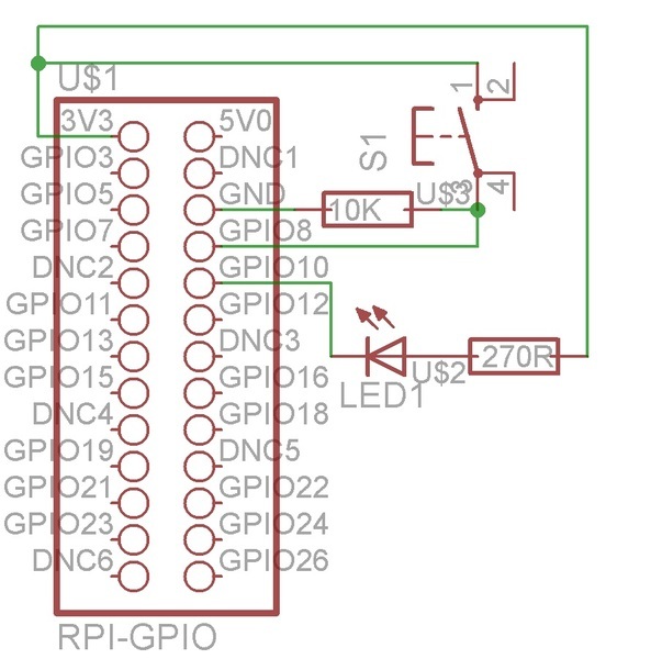
GPIO, which stands for General Purpose Input/Output, allows a GPIO pin to be set to high (1) by connecting it to a voltage supply or low (0) by connecting it to ground. The Raspberry Pi can configure the pin...