
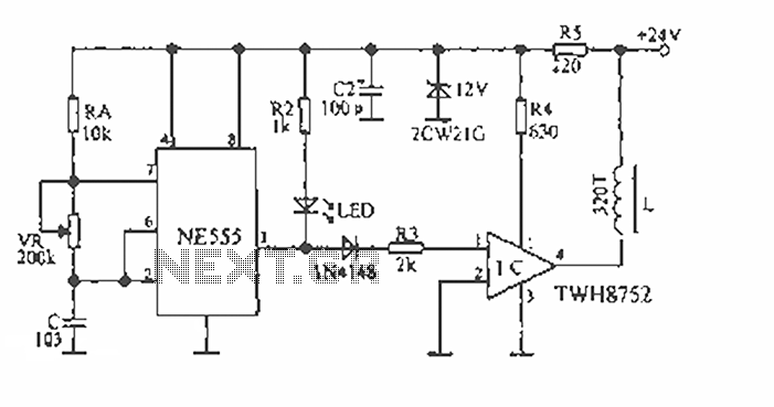
Side tone coupling circuit diagram

The receiver sidetone circuit is an essential component in telephone systems, ensuring that users receive auditory feedback of their own voice during conversations. This feedback is crucial for maintaining natural communication, as it helps users modulate their speaking volume and prevents them from feeling isolated from the conversation.
In the circuit, inductors L1 and L2 are strategically designed with an unbalanced turns ratio to create a differential in the magnetic fields they generate. This differential is critical for inducing a controlled amount of sidetone into inductor L3. The resistor R plays a significant role in this process; by adjusting its value, the circuit can be fine-tuned to achieve the desired level of sidetone without matching the line impedance, which could lead to undesirable feedback or distortion.
The output from inductor L3 is then fed back into the receiver, allowing the user to hear their own voice. The level of sidetone must be carefully calibrated; too much sidetone can cause confusion and lead to lower speaking volumes, while too little can result in the user believing the line is dead, prompting them to raise their voice unnecessarily.
Overall, the design of the sidetone coupling circuit is a delicate balance of inductive coupling, resistance, and impedance matching, all aimed at enhancing the user experience in telephone communications.Side tone coupling:In telephones, it is the hearing of one`s voice in the receiver when one speaks. Too muchside tonemake people speak lower and can cause feedback. Too littleside toneand people may think the phone is not working or may shout. Figure This is a simplified schematic diagram of a receiver sidetone circuit. Because curren t will not flow through a balanced circuit, the turns ratio of inductors L1 and L2 is unbalanced by a predetermined amount and the value of resistor R is changed so as not to match the line impedance. This way, a controlled amount of signal can be induced into L3 to be used as receiver sidetone. 🔗 External reference
Related Circuits
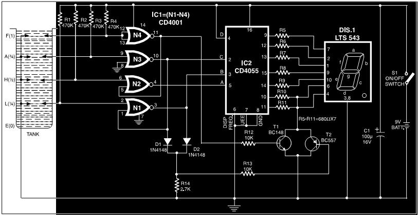
This circuit is a fluid level indicator that displays each level using meaningful English letters. It employs a seven-segment display to represent the letters E for empty, L for low, H for half, A for above average, and F...
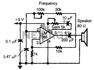
An LM386 audio power IC is configured as a feedback oscillator. It can operate with a supply voltage ranging from 6 to 12 V. The circuit is capable of driving a loudspeaker. The LM386 is a low-voltage audio power amplifier...
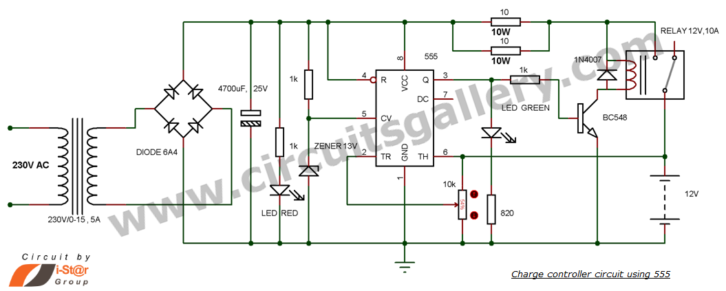
This is a simple DIY charge controller schematic created in response to a request from one of the readers on our Facebook page. The primary component of this automatic battery charger circuit is a 555 timer, which compares the...
The device is designed to accelerate the defrosting process of fish, meat, and other foods by utilizing audio vibrations. This method allows for defrosting in warm water, significantly reducing the time required compared to conventional methods, while preserving the...
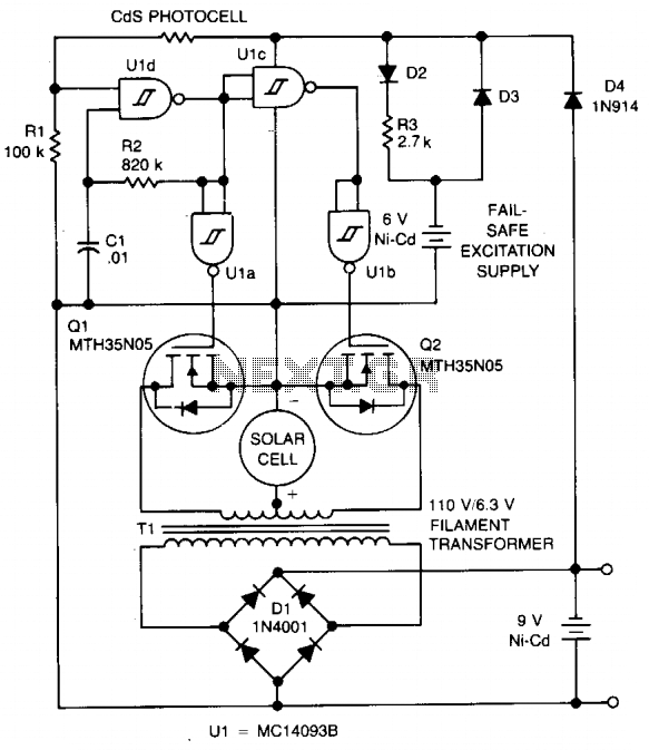
The circuit charges a 9-V battery at approximately 30 mA per input ampere at 0.4 V. U1, a quad Schmitt trigger, operates as an astable multivibrator to drive push-pull MOSFET devices Q1 and Q2. Power for U1 is derived...
The TDA2040 is a monolithic integrated circuit housed in a Pentawatt package, designed for use as an audio class AB amplifier. It typically delivers an output power of 22W (with a distortion factor of 0.5%) at a supply voltage...