
Simple Amplified Field Strength Meter Circuit
The described circuit functions as a bridge amplifier utilizing a Field Effect Transistor (FET) to amplify DC signals. The bridge configuration allows for precise measurement and nulling of the output, making it suitable for applications requiring high sensitivity and accuracy. The incorporation of R4 as a nulling resistor ensures that the output can be calibrated to zero, facilitating accurate readings regardless of the input variations.
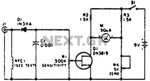
The switch J1, when short-circuited, allows for direct measurement without the influence of any additional resistance that may be introduced by the meter, thus ensuring that the circuit operates within its optimal parameters. The choice of a 50-mA meter is critical as it aligns with the expected output current range, ensuring that the circuit can effectively drive the meter without risking damage from overcurrent.
RFC1, the RF choke, plays an essential role in filtering out unwanted high-frequency signals, allowing only the desired frequency range to pass through. The specification of a 2.5-mH RF choke is indicative of its capability to support broadband operations, making the circuit versatile for various frequency applications.
Resistor R1's function as a sensitivity control is vital for adjusting the gain of the amplifier. By varying the resistance, the user can fine-tune the circuit's response to different input levels, enhancing its adaptability in diverse applications.
The use of a small whip antenna, ideally 2 feet or less, further complements the circuit's design by providing a compact and effective means of signal reception. This type of antenna is particularly suitable for portable applications or environments where space is constrained, ensuring that the circuit remains functional without requiring extensive installation or setup.
Overall, this circuit design exemplifies a practical approach to building a sensitive and adaptable DC amplifier suitable for a range of applications in electronics. This circuit uses a FET as a dc amplifier in a bridge circuit. R4 is set for meter null with J1 short circuited. Any surplus 50-mA meter can serve in this circuit. RFC1 is any suitable RF choke for the band in use. A 2.5-mH RF choke will do for broadband operation. R1 is a sensitivity control. The antenna can be any small whip antenna (2 ft or less). 🔗 External reference
Related Circuits
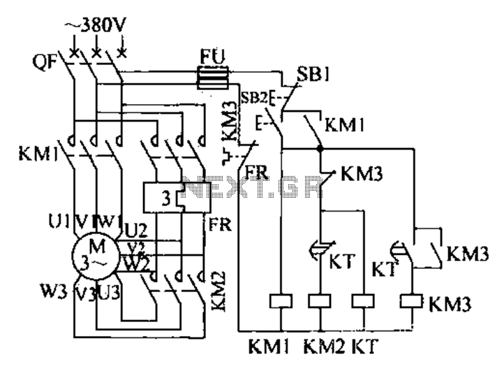
The extended delta decompression starter is designed to manage the operation of a three-phase motor during startup. It involves the initial connection of the motor's three-phase winding set to facilitate a reduced voltage startup, which is achieved through a...
The RF signal is divided into two signals that are shifted 90 degrees out of phase (one at plus 45 degrees and one at minus 45 degrees). Both signals are then mixed to audio frequencies. The two audio signals...
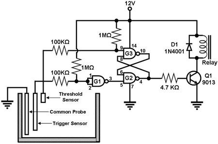
Figure 1 illustrates a circuit designed to monitor the water level in a tank and control a water pump accordingly. The primary component of the circuit is the CD-4011 Quad NAND gate, with three of its gates utilized as...
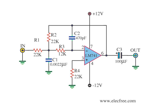
This circuit filters low frequencies below 10 kHz using the highly popular operational amplifier IC uA741. It is convenient for applications that require the conversion of analog signals to digital or vice versa. In digital sound systems, this circuit...
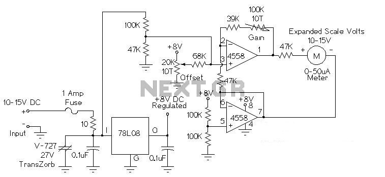
This circuit is used to measure the voltage on a 12V (nominal) lead acid rechargeable battery system. It was specifically designed for use in solar powered systems, but is general enough that it can be used for automotive or...
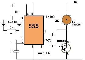
This project utilizes a 555 timer to control the speed of a 6-volt DC motor. Speed adjustment is achieved by rotating a 50 kΩ potentiometer either to the left or right. The circuit employs a 555 timer configured in astable...
Warning: include(partials/cookie-banner.php): Failed to open stream: Permission denied in /var/www/html/nextgr/view-circuit.php on line 713
Warning: include(): Failed opening 'partials/cookie-banner.php' for inclusion (include_path='.:/usr/share/php') in /var/www/html/nextgr/view-circuit.php on line 713